
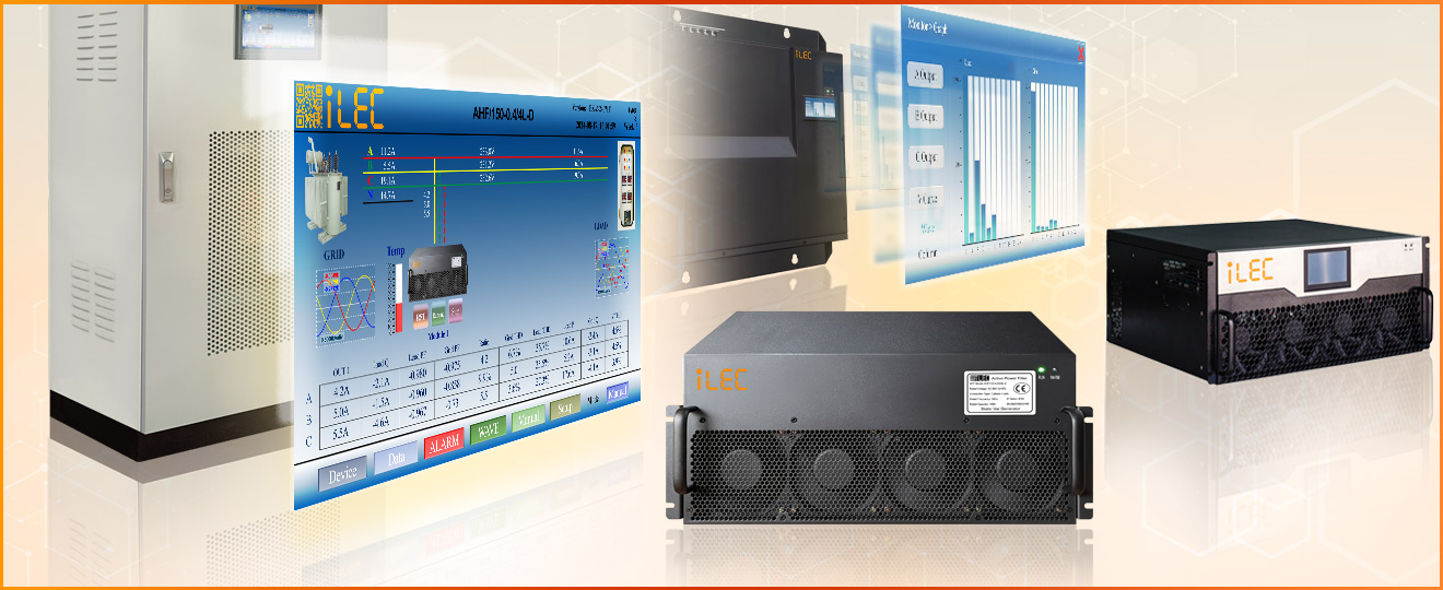
ACTIVE HARMONICS FILTER
Model AHF
(Wall mount & Rack mount)
Power Quality: Active Harmonics Filter (AHF), Static Var Generator (SVG), Current Imbalance Solution, Voltage sag and voltage corruption solution, Transformer balance solution.
INTRODUCTION TO POWER QUALITY AND HARMONICS
■ Power Quality
Electrical power quality is any abnormal behavior on a power system arising in the form of voltage or current, which affects the normal operation of electrical or electronic equipment.
Power quality is any deviation of the voltage or current waveform from its normal sinusoidal wave shape.
Power quality has been defined as the parameters of the voltage that affect the customer’s supersensitive equipment.
Most common power quality problems:
- Voltage sag
- Voltage swell
- Voltage Flicker
- Harmonics
- Over voltage
- Under voltage
- Transients

■ Ideal waveform and harmonics waveform
- Most automation devices and internet devices use electricity. For these devices to operate stably, the quality of electricity must be guaranteed.
- Power quality is best when both voltage and current have ideal sine waveforms.
- Sine wave ensures that the voltage and current values vary evenly and are not too sudden. The slow and steady change helps components and equipment operate stably and durably.

- However, many new generation electrical devices cause power quality problems. These devices are often referred to as non-linear loads. Examples include controlled rectifiers, inverters, and switching power supplies.
- Each type of equipment usually generates harmonics with different frequencies. Usually these frequencies are multiples of the fundamental harmonic. For example, the 1st order fundamental wave has a frequency of 50Hz, common wave frequencies are usually 150Hz (3rd order), 250Hz (5th order), 350Hz (7th order), 550Hz (11th order), 650Hz (13th order)

■ Common phenomenon caused by harmonics problems
- Power capacitor overheat fault
- Solar inverter restarts many times even though voltage is within allowable range
- PLC jump or reset without reason
- Abnormal action of circuit breaker and variable speed drive
- Rising of equipment failure rate
- Neutral cable overheat and big current even though line currents are balance
- Precision instruments cannot work properly or are damaged
- Overheat damage of equipment such as motor and transformer (not in overload condition)
- The life of motor is shortened
- Equipment can not reach the rated power, and the efficiency is low
- Too high switchgear temperature rise and noisy
- Sudden shutdown of the running inverter.
- Precision instruments cannot work properly or are damaged
■ Benefits of harmonic treatment to improve power quality
- Meet the requirements of power supply department on power consumption.
- Reduce the economic losses caused by equipment misoperation.
- Improve the efficiency and reliability of equipment operation.
- Reduce heating of electric equipment, prolong insulation aging time
- Increase service life of equipment, and reduce maintenance cost of equipment
- Reduce the resonance probability of compensation capacitors in the power grid
- Reduce the electromagnetic interference caused by harmonic
- Improve the stability of small current systems (sensitive systems)
■ Benefits of power factor improvement (VAR correction)
- Ensure the power factor of the system up to the national standard
- Reduce grid line losses and improve upstream transformer capacity
- Reduce the current and voltage drop, release the capacity of transformer and generator
- Improve the utilization rate of equipment and improve the stability of power grid
■ Three-phase imbalance correction
- Reduce neutral current caused by imbalance load and prevent fire risk;
- Reduce voltage imbalance faults, reduce overload and overheat of transformer’s coil
ILEC ACTIVE HARMONICS FILTER (AHF)
■ AHF working principle
When an ideal sine source suply to a linear load, The current waveforms are sine both sides.

When an ideal sine source suply to a none-linear load, The harmonics current from load will distort the total current.

The active power filter monitors the load current real-time through the external current transformer CT, and extracts the harmonic component of the load current through the internal DSP computing, then sends it through the PWM signal to the internal IGBT, the inverter produces a current equal to the load harmonic and opposite to the harmonic direction and injects the current into the grid to compensate the harmonic current realizing the function of harmonic control.

In the electrical system there are many harmonic orders, the working principle in bar graph is shown as below.

The process of AHF separating harmonics of and processing them as shown below:

■ ILEC AHF features
- Harmonic compensation up to 50th order, 14 different harmonics at the same time
- Fast reactive power compensation, support unbalance system
- Load balancing between phases and unloaded neutral wire
- Compact design, 3 level topology
- Modular system extendable, support up to 6 modules for one HMI.
- Grid resonance detection and prevention using hardware and software
- Dual DSP+FPGA Architecture with leading algorithm, fast response
■ ILEC AHF Ordering code structure

ILEC AHF Current rating seclection table:

◾ILEC AHF Technical parameters
| ITEM | 400VAC system |
| Input voltage (VLL) | Un (-10% ~ +10%) |
| Grid type | 3P3W (0.4/3L) / 3P4W (0.4/4L) |
| Grid frequency | 50Hz / 60Hz (-10% ~ +10%) |
| Maximum parallel modules | 6 modules per HMI controller / unlimited number of controller and modules |
| Overall efficiency | >= 97% |
| Current transformer | 50/5A to 5000/5A (more range on request) |
| Circuit topology | Tri-level |
| Rated capacity | 30A, 50A, 75A, 100A, 150A (check table 2.2 for update) |
| Filter functions | Harmonics filter / Reactive power compensation / Phase balance function |
| Filter harmonics order | 2 ~ 50, maximum 14 orders (selectable) at the same time |
| Filter Amplitude adjustment | Maximum 150% for each order (Default recommended 80–90%) |
| Filter phase adjustment | 2 to 50 degree |
| Filtering ability | THDi< 5% |
| Response time | < 15ms |
| Target power factor | -1 to 1 (Capacitive and Reactive) (Recommended -0.95 to -0.99 / 0.95 to 1.00) |
| kVAR compensator mode | support |
| Control algorithm | FFT, intelligent FFT algorithm, instantaneous reactive algorithm |
| Switching frequency | 20kHz |
| Cooling mode | Forced air cooling (built-in fan) |
| Noise level | < 65dB |
| Communication interface | RS485, Ethernet (optional) |
| Communication protocol | Modbus-RTU |
| Monitoring mode | Support centralized monitoring and independent monitoring (optional) |
| Display interface | 7, 10 inch centralized monitoring LCD touch screen, 4.3 inch independent |
| Protection function | Over voltage / under voltage protection, short circuit protection, inverter bridge reverse protection and overcompensation protection |
| Fault alarm | Yes, up to 256 alarm records |
| Fixed mode | Rack mounted type, wall-mounted type |
| Altitude | rated capacity for below 1500m, 1500–4000m: reduced by 1% every 100m |
| Operating temperature | |
| Relative humidity | 5% ~ 95%, no condensation |
| Protection class | IP20 |
CONNECTION DIAGRAM AND MODULAR DESIGN
■ Connection diagram


■ Modular design

EQUIPMENT DESCRIPTION
■ 0.4kV and 0.48kV AHF
Equipment introduction


| No. | Name | Remark |
| 1 | Front panel | AHF Module front panel |
| 2 | Status indicator | Device running status display |
| 3 | Cooling fan | / |
| 4 | Handle | (only for rack-mounted AHF module) |
| 5 | Rack mounting ear | Rack-mounted module mounting fixed (Rack-mounted only) |
| 6 | Cooling duct | / |
| 7 | Main circuit input terminal | L1, L2, L3 |
| 8 | Neutral input terminal | N² |
| 9 | Ground wire input terminal | PE |
| 10 | Current sampling input terminal | CT1/CT1N, CT2/CT2N, CT3/CT3N |
| 11 | Auxiliary circuit terminal | DC 24V auxiliary power supply, RS845 communication |
| 12 | DIP switch | Communication address setting |
| 13 | Cooling duct | / |
| 14 | Wall mounting ear | Wall-mounted module mounting fixed (Wall-mounted only) |
■ 0.69kV AHF
Equipment introduction

| No. | Name | Remark |
| 1 | Status indicator | Device running status display |
| 2 | Front panel | AHF Module front panel |
| 3 | Rack mounting ear | Rack-mounted module mounting and fixed |
| 4 | Handle | Rack-mounted AHF module front handle |
| 5 | Ground wire input terminal | PE |
| 6 | Neutral input terminal | N |
| 7 | Main circuit input terminal | L1, L2, L3 |
| 8 | Upper cooling duct | Upper heat dissipation |
| 9 | Current sampling input terminal | CT1/CT1N, CT2/CT2N, CT3/CT3N |
| Auxiliary circuit terminal | DC 24V auxiliary power supply, RS845 communication | |
| DIP switch | Communication address setting | |
| 10 | DIP switch | Bottom fan |
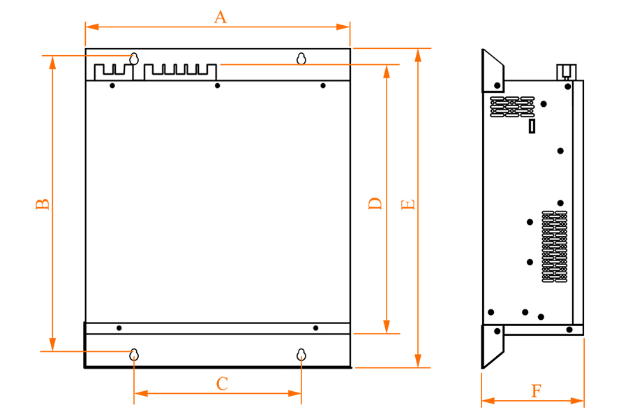
AHF MODULE DIMENSIONS
■ 0.4 kV AHF Module Dimensions
Wall-mounted design
| 0.4kV | Wall-mounted module dimension (Unit: mm) |
|||
|---|---|---|---|---|
| 30A / 50A | 75A / 100A | 150A | ||
| A | 460 | 540 | 540 | |
| B | 440 | 524 | 524 | |
| C | 62 | 85 | 110 | |
| D | 86 | 190 | 219 | |
| E | 420 | 500 | 500 | |
| F | 483 | 545 | 551 | |
| G | 451 | 507 | 515 | |
| H | 420 | 478 | 479 | |
| I | 86 | 135 | 145 | |
Rack-mounted design
| 0.4kV | Rack-mounted module dimension (Unit: mm) |
|||
|---|---|---|---|---|
| 30A / 50A | 75A / 100A | 150A | ||
| A | 424 | 504 | 504 | |
| B | 491 | 543 | 567 | |
| C | 230 | 315 | 315 | |
| D | 445 | 507 | 513 | |
| E | 541 | 584 | 608 | |
| F | 88 | 191 | 220 | |

■ 0.48 kV AHF Module Dimensions
Wall-mounted design
| 0.48kV | Wall-mounted module dimension (unit: mm) |
|||||||||
|---|---|---|---|---|---|---|---|---|---|---|
| A | B | C | D | E | F | G | H | V | ||
| AHF 100A | 620 | 604 | 580 | 190 | 135 | 85 | 596 | 556 | 520 | |

Rack-mounted design
| 0.48kV | Rack-mounted module dimension (unit: mm) |
|||||||||
|---|---|---|---|---|---|---|---|---|---|---|
| A | B | C | D | E | F | G | H | V | ||
| AHF 100A | 620 | 604 | 580 | 190 | 135 | 85 | 596 | 556 | 520 | |

■ 0.69 kV AHF Module Dimensions
Wall-mounted design
| 0.69kV | Wall-mounted module dimension (unit: mm) |
|||||||
|---|---|---|---|---|---|---|---|---|
| A | B | C | D | E | F | G | H | |
| AHF 100A | 540 | 524 | 175 | 250 | 500 | 743 | 703 | 674 |

Rack mounted design
| 0.69kV | Rack mounted module dimension (unit: mm) |
|||||
|---|---|---|---|---|---|---|
| A | B | C | D | E | F | |
| AHF 100A | 504 | 729 | 315 | 703 | 769 | 262 |

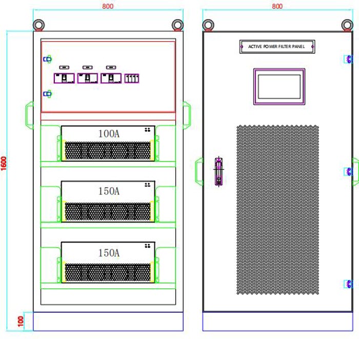
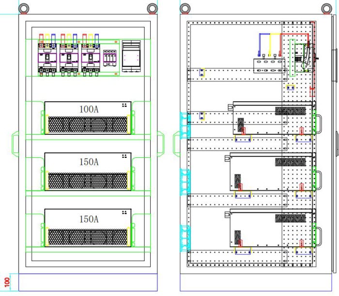
TYPICAL DESIGN AND RESULTS
■ Typical cabinet design
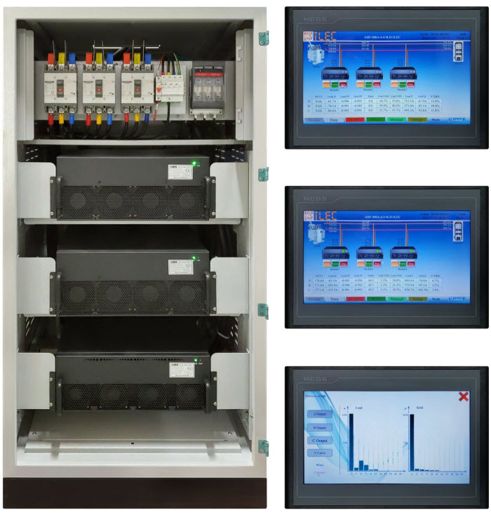
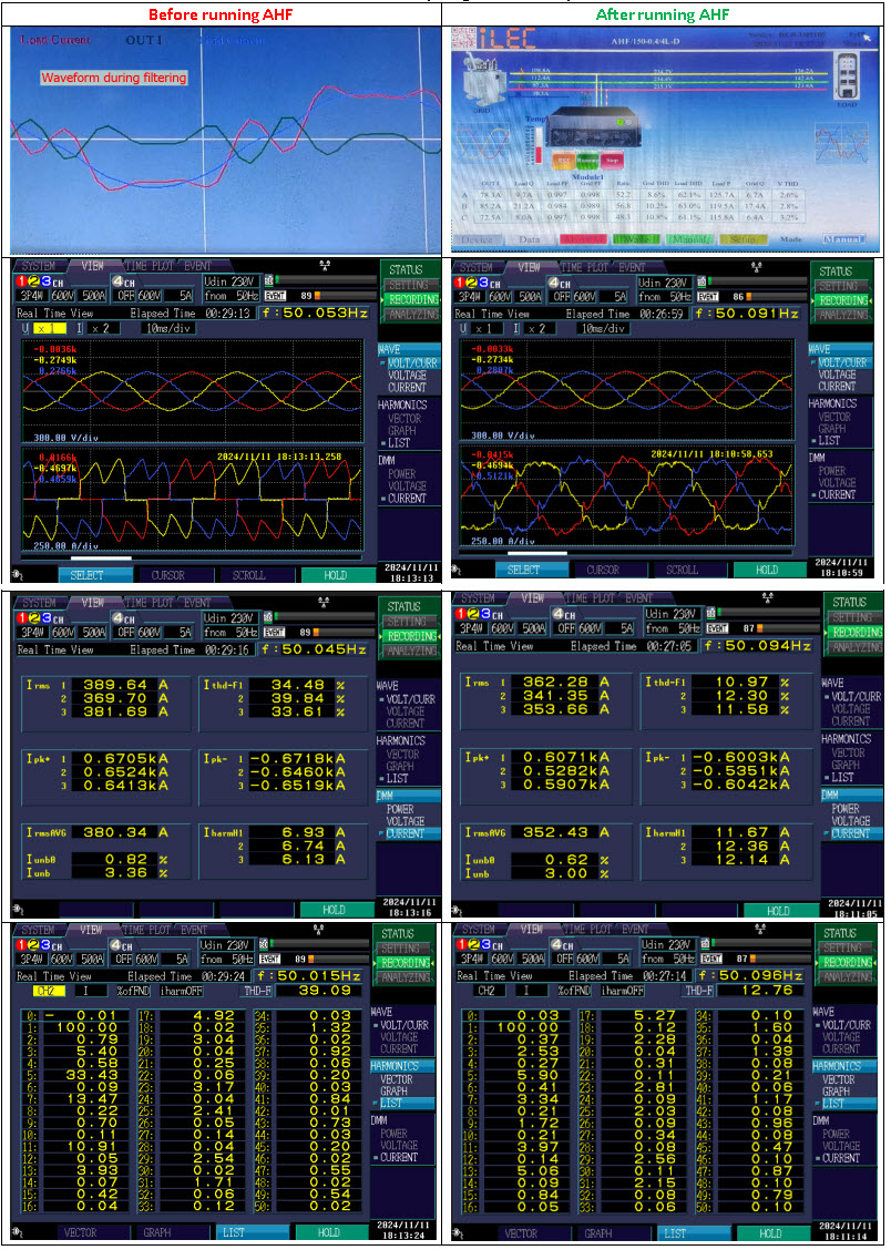
■ Testing results
Cabinet 3x150A and cabinet 2x150A + 1x100A (cambodia customer)
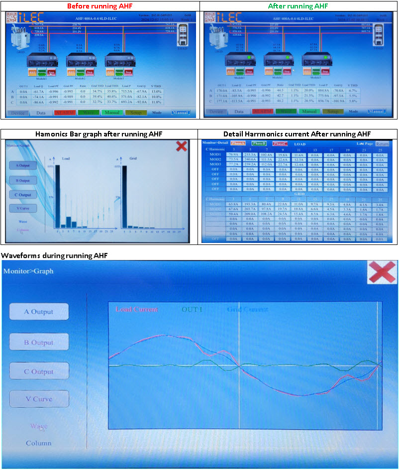
Modul 150A installed at Innovance inverter 350kW (Daklak, Vietnam)
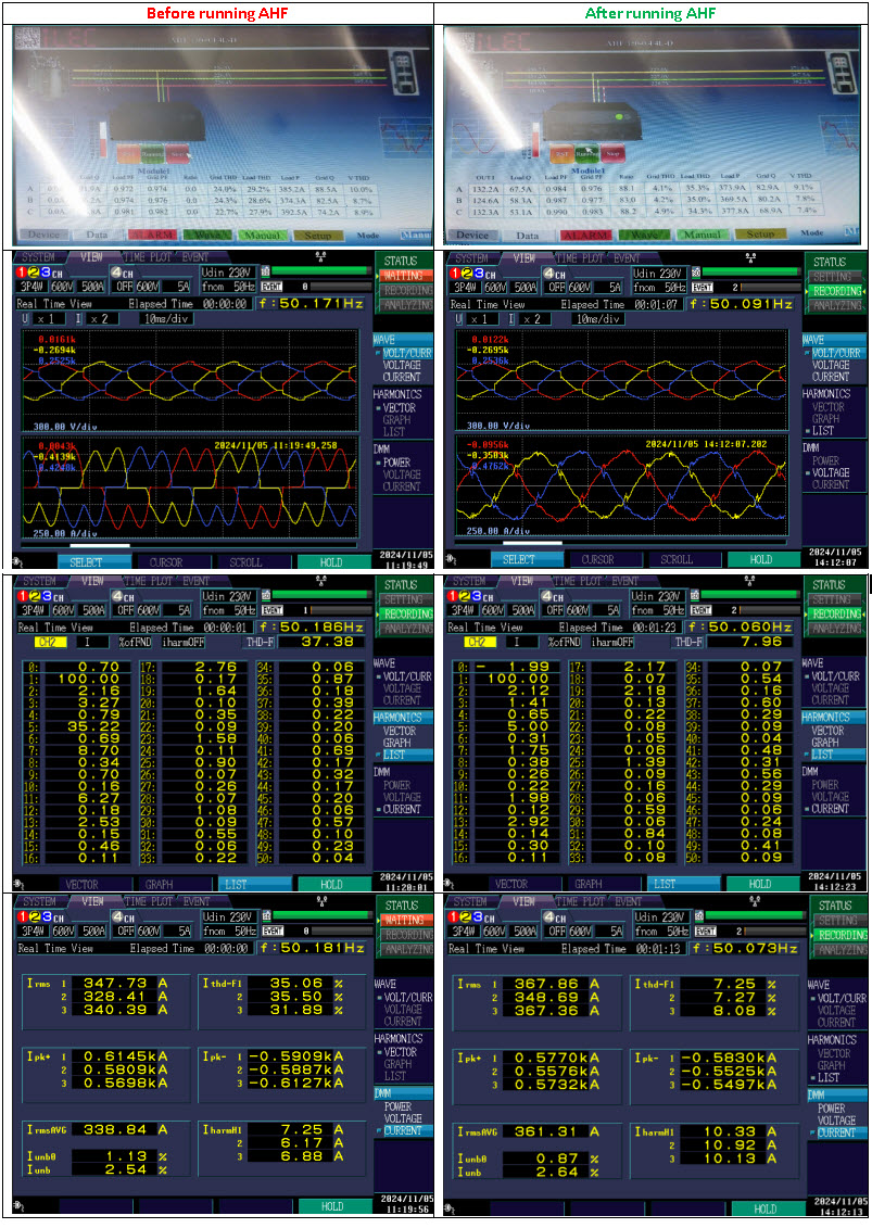
Modul 150A installed at Sinamic G120x inverter 350kW (Dong nai, Vietnam)
Resources & Support
- Technical document: iLEC AHF Models
- Pricing & Ordering: View Details

- Written by: Huyen
- Parent Category: product
- Hits: 127