RT6-D10-U flasher relays are designed for every usage (industry, house, plant etc..) which needs double timing controll.
Specifications
PARAMETER
VALUE
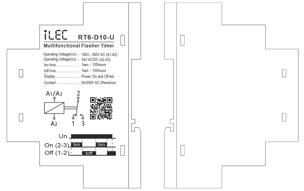
Operating voltage (Un)
AC 160V–260V (A1-A2); AC/DC 24V (A3-A4)
Operating frequency
50/60Hz
Operating power
< 6VA
Operating temperature
-20ºC ~ 55ºC
Ton time
1sec – 100hrs
Toff time
1sec – 100hrs
Display
Power, On and Off led
Connection type
Terminal connection
Weight
max. 110 gr.
Contact
5A/250V AC (Resister Load)
Mounting
Vertical assembled on the panel (or on the DIN rail)
Operating Altitude
< 2000m
Cable diameter
1.5 mm²
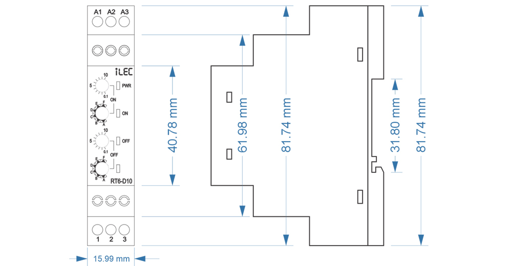
Dimension
Device Usage and Working Principle
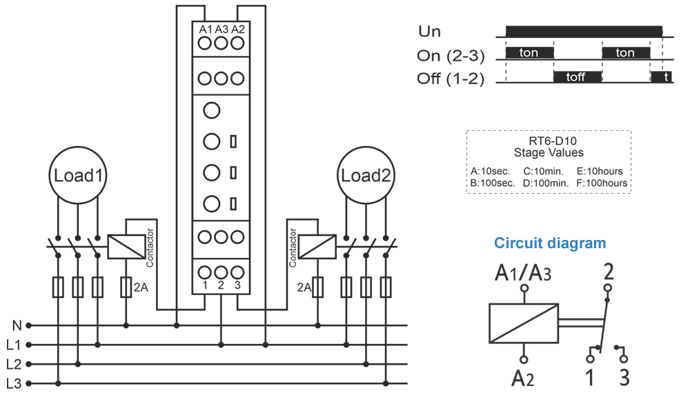
Make the connections according to the diagram.
Max.On Time: Sets the stage of “on” and display the maximum “on” time.
Max.Off Time: Sets the stage of “off” and display the maximum “off” time.
ton: Divides the “on” time by 10 and multiples by displayed value.
toff: Divides the “off” time by 10 and multiples by displayed value.
* Example: Working time(on) is 75minutes, waiting time (off) is 60seconds.
Turn on the stage button to 100m and ton button between 7-8. “On” time will be adjusted to 75 minutes.
Turn off the stage button to 100s and toff button to 6. “Off” time will be adjusted to 60 seconds.
* Note: In order to adjust much sensitive higher time values, set “t” by chronometer in low stages and increase the stage to the time required.
* Example: Working time (on) 7,5 hours and waiting time (off) is 50 minutes.
Turn on the “on” stage button to 10s. and “ton” button between 7-8. Power on the device and check for 7.5 seconds with chronometer. If it is high or low, re-set “ton”.
Power on and check again. Later, turn on the “on” stage button to 10h, in this case “on” time will be much sensitive.
Turn on the “off” stage button to 10s. and “toff” button to 5. Power off the device and check for 5 seconds with chronometer.
If it is high or low, re-set “toff”. Power on and check again. Later, turn off the “off stage button to 100m, in this case “on” time will be much sensitive.
After time settings, power on the device. at the beginning, “on” time will count and “on” led will flash. While counting, relay contact out is (NO) 3 pole.
When the counting finishes, “off” time will start to count and off led flashes. While counting “off” time, relay contact out is (NC) 1 pole.
Till the power is off, device keeps counting on and off times in turn.
Typical Connection Diagram
Maintenance
Switch off the device and release from connections.
Clean the trunk of device with a swab.
Don’t use any conductor or chemical might damage the device.
Make sure device works after cleaning.
Warnings
Please use the device according to the manual.
Don’t use the device in wet.
Include a switch and circuit breaker in the assembly.
Put the switch and circuit breaker nearby the device, operator can reach easily.
Mark the switch and circuit breaker as releasing connection for device.