

WEEKLY TIME SWITCH
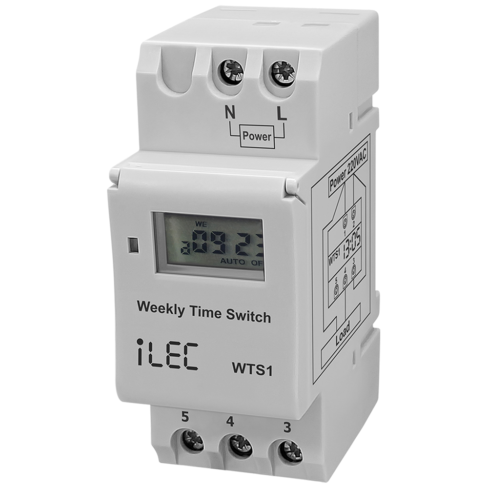
Model WTS1
General description
- The WTS1 is a programmable digital timer switch with relay output.
- It can be used to turn on or off lights, appliances or other small loads on specified days of the week and times.
- The switching on and off times are repeated daily and (or) weekly.
- The timer support up to 16 different programs daily / weekly schedules.
- Manual mode is available to overrule the programmed relay events.
- A super capacitor inside the timer switch keep the RTC running at least 150 hours (700 hours expected) and it will be charged when the timer is connected to an AC power.
- The DIN rail mount of this timer switch makes it suitable for power management in a control panel.
Specifications
| Parameters | |
| Number of circuits | Change over switch (SPDT) |
| Rated voltage | 110–220VAC, 50/60Hz |
| Power consumption | 4.5VA (max.) |
| Operation | 16 ON + 16 OFF |
| Pulse width | 1min – 23h 59min |
| Daily program | 16 combination |
| Clock error | ≤2 sec/day (25ºC) |
| Switching contact | 1 changeover switch |
| Contact rating | 16 @250VAC (Resistive) 8A @250VAC (pf=0.8IND) |
| Battery reserve | Warranty 150 hours, espected > 700hours (Rechargeable) |
| Load capacity | 30(16A) 240VAC (Ohmic load cosφ=1) |
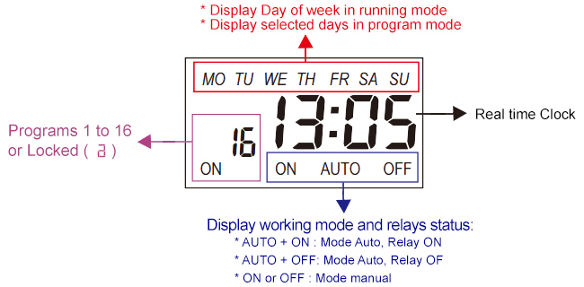
| Display | LCD realtime Hour/Minute and ON / AUTO / OFF
* Days of week + Real time clock * Auto / On / Off * Relay status (ON or OFF) |
| Service life | Mechanically & Electrically: 10.000 hours |
| Operating temperature | 10ºC ~ 55ºC |
| Humidity | 35 ~ 85% RH |
| Installation | DIN rail 35mm |
| Dimension | 87 x 36 x 69 (mm) |
Connection terminals
| ● L, N : | Auxiliary power supply 110–220VAC ON LED will light when power is available. |
| ● 3, 4, 5 : | Changeover switch SPDT. Terminal 3 is Common 3-4: NO contact 3-5: NC contactable |
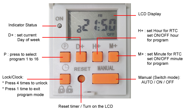
Front Panel Description
LCD display explanation
Operating method
- First time use this timer switch, please input power and left battery recharge.
- After then press " RESET "
- Clock setting: Press " D+ " key, " M+ " key respectively to adjust clock of Timer to accurate ADTE, HOUR, MINUTE
Resources & Support
- Technical document: iLEC WTS1
- Operating & Apllications: iLEC WTS1
- Pricing & Ordering: View Details

Review iLEC WTS1 – Weekly Timer Switch
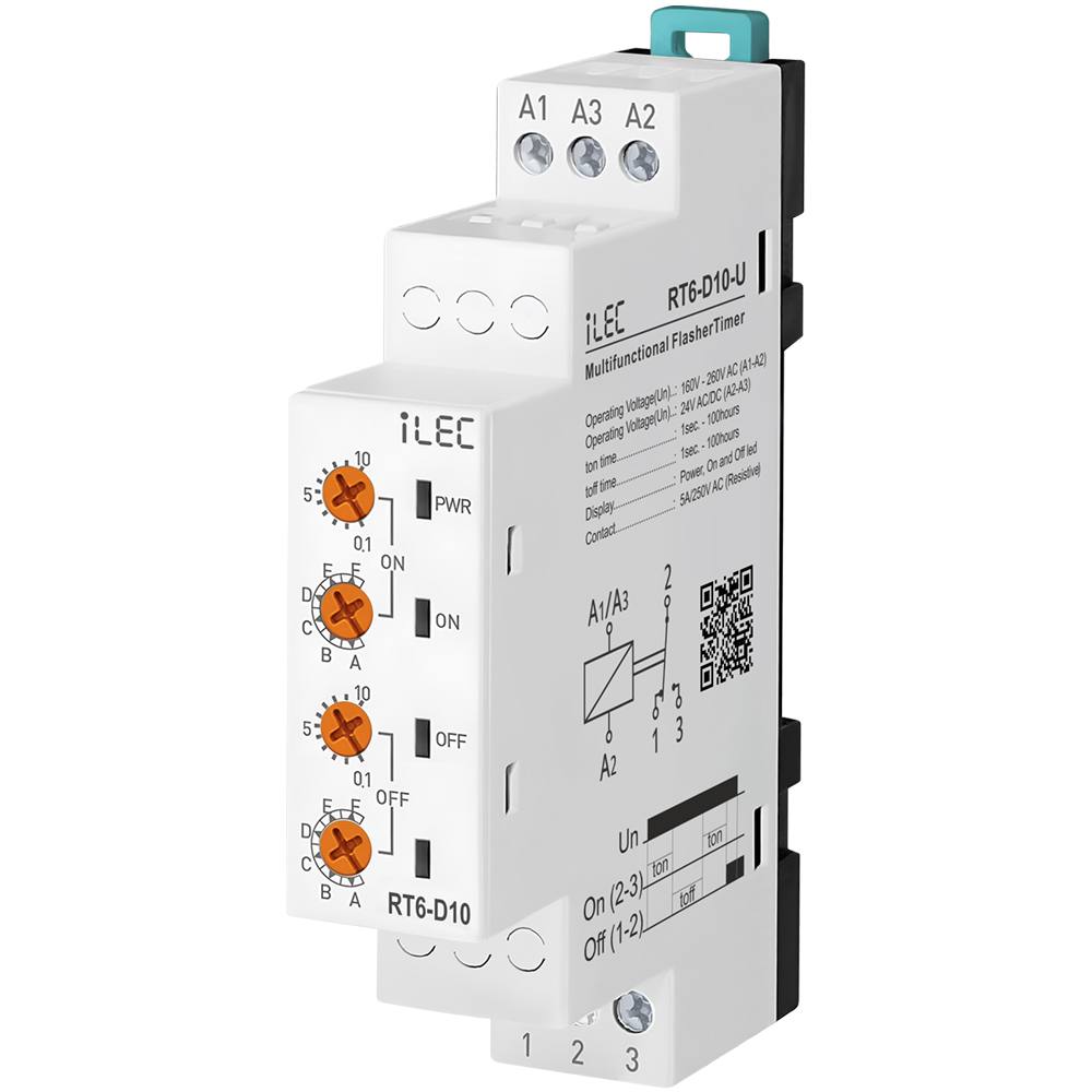
MULTIFUNCTIONAL FLASHER TIMER
Model RT6-D10-U
Introduction
RT6-D10-U flasher relays are designed for every usage (industry, house, plant etc..) which needs double timing controll.
Specifications
| PARAMETER | VALUE |
| Operating voltage (Un) | AC 160V–260V (A1-A2); AC/DC 24V (A3-A4) |
| Operating frequency | 50/60Hz |
| Operating power | <6VA |
| Operating temperature | -20ºC ~ 55ºC |
| Ton time | 1sec – 100hrs |
| Toff time | 1sec – 100hrs |
| Display | Power, On and Off led |
| Connection type | Terminal connection |
| Weight | Max. 110 gr. |
| Contact | 5A/250V AC (Resister Load) |
| Mounting | Vertical assembled on the panel (or on the DIN rail) |
| Operating Altitude | <2000m |
| Cable diameter | 1.5 mm² |
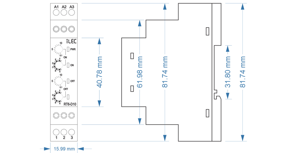
Dimension
Device Usage and Working Principle
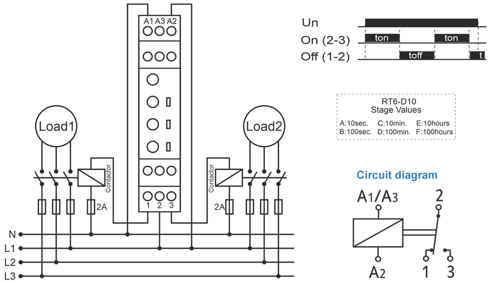
- Make the connections according to the diagram.
- Max.On Time: Sets the stage of “on” and display the maximum “on” time.
- Max.Off Time: Sets the stage of “off” and display the maximum “off” time.
- ton: Divides the “on” time by 10 and multiples by displayed value.
- toff: Divides the “off” time by 10 and multiples by displayed value.
* Example: Working time(on) is 75minutes, waiting time (off) is 60seconds. - Turn on the stage button to 100m and ton button between 7-8. “On” time will be adjusted to 75 minutes.
- Turn off the stage button to 100s and toff button to 6. “Off” time will be adjusted to 60 seconds.
* Note: In order to adjust much sensitive higher time values, set “t” by chronometer in low stages and increase the stage to the time required.
* Example: Working time (on) 7,5 hours and waiting time (off) is 50 minutes. - Turn on the “on” stage button to 10s. and “ton” button between 7-8. Power on the device and check for 7.5 seconds with chronometer. If it is high or low, re-set “ton”.
- Power on and check again. Later, turn on the “on” stage button to 10h, in this case “on” time will be much sensitive.
- Turn on the “off” stage button to 10s. and “toff” button to 5. Power off the device and check for 5 seconds with chronometer.
If it is high or low, re-set “toff”. Power on and check again. Later, turn off the “off stage button to 100m, in this case “on” time will be much sensitive.
After time settings, power on the device. at the beginning, “on” time will count and “on” led will flash. While counting, relay contact out is (NO) 3 pole.
When the counting finishes, “off” time will start to count and off led flashes. While counting “off” time, relay contact out is (NC) 1 pole.
Till the power is off, device keeps counting on and off times in turn.
Typical Connection Diagram
Maintenance
- Switch off the device and release from connections.
- Clean the trunk of device with a swab.
- Don’t use any conductor or chemical might damage the device.
- Make sure device works after cleaning.
Warnings
- Please use the device according to the manual.
- Don’t use the device in wet.
- Include a switch and circuit breaker in the assembly.
- Put the switch and circuit breaker nearby the device, operator can reach easily.
- Mark the switch and circuit breaker as releasing connection for device.
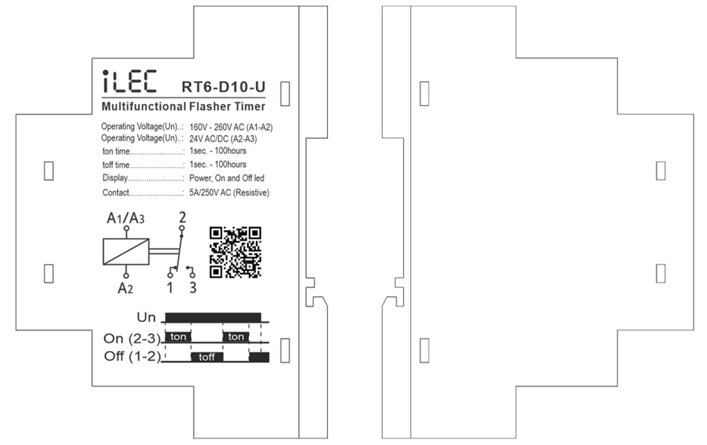
External description
Resources & Support
- Technical documents: Model RT6-D10-U
- Reference Articles: Wiring and Installation Guide
- Pricing & Ordering: View Details
Review Relay iLEC RT6-S10-U
MULTIRANGE ON DELAY TIMER RELAY
Model RT6-S10-U
Introduction
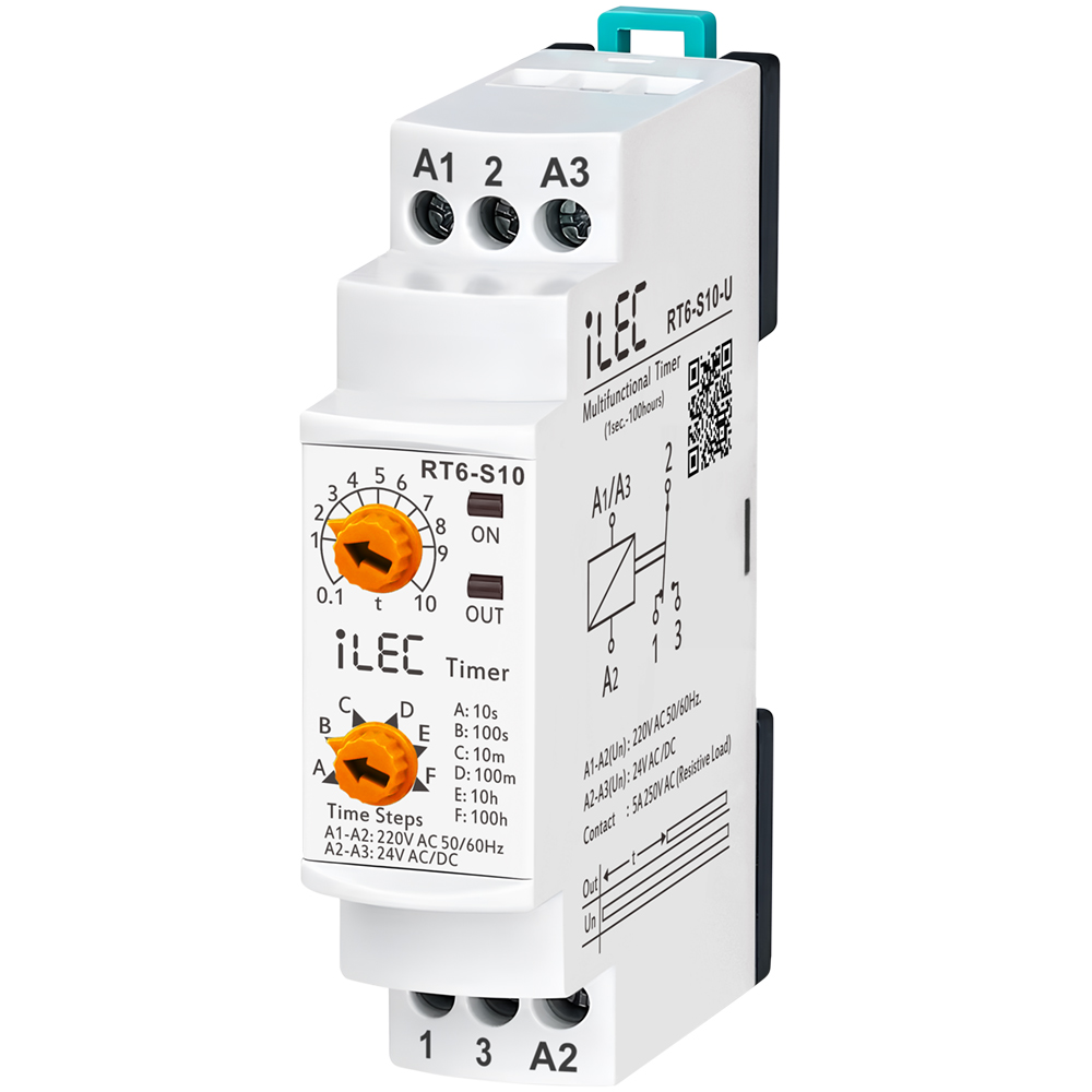
RT6-S10 and RT6M-S10 timer relays are used in all fields (industry, house, plant etc.) need controlls related to the time.
Specifications
| PARAMETER | VALUE |
| Operating voltage (Un) | AC 150V–260V and AC/DC 24V |
| Operating frequency | 50/60Hz |
| Operating power | <4VA |
| Operating temperature | -20ºC ~ 55ºC |
| Timer (t) | 10sec, 100sec, 10min, 100min, 10hrs, 100hrs |
| Display | On led and Out (RLY ) led |
| Connection type | Terminal connection |
| Weight | Max. 120 gr. |
| Contact | 5A/250V AC (Resister Load) |
| Mounting | Assembled on the DIN rail |
| Operating Altitude | <2000m |
| Cable diameter | 1.5 mm² |
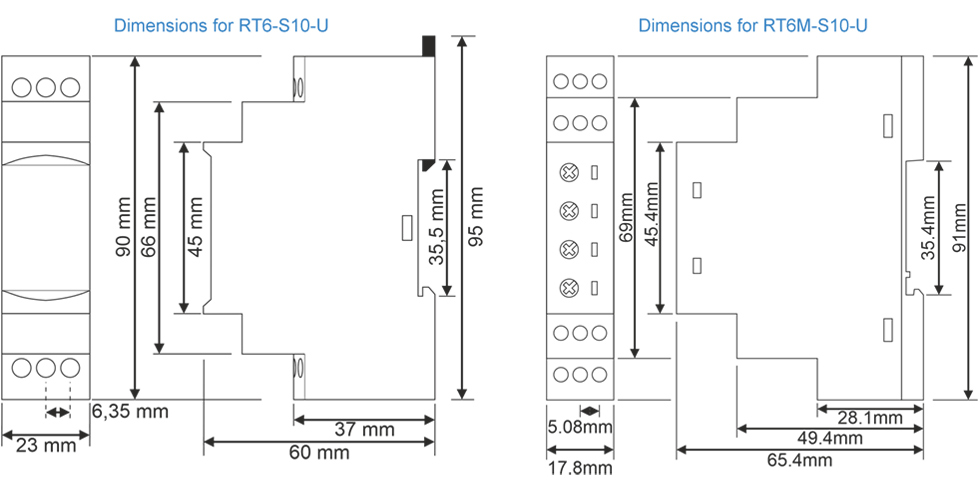
Dimension
Usage of Device and Working Principle
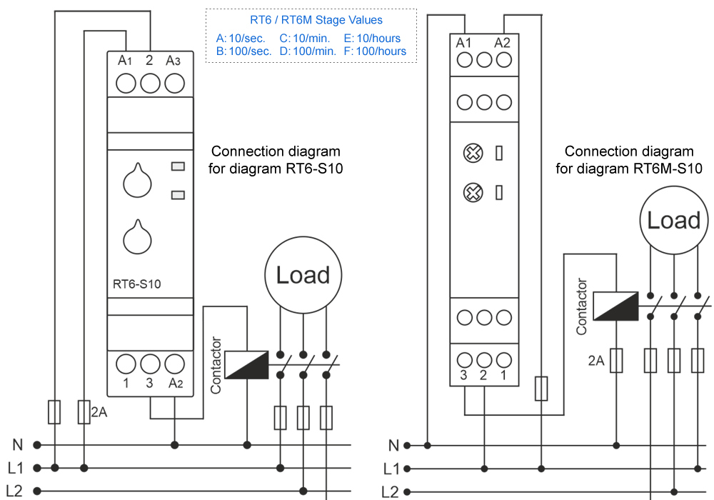
- Make the connections according to the diagram.
- Max.Time (Time Steps, TS ): Adjusts the stage and display the max.time.
- [ t ]: Divides the stage by 10 and multiply with displaying value.
* Example: Time is 75 minutes. - Make stage button to 100m (100 minutes) and turn “t” button between 7-8. In this case time is adjusted to 75 minutes.
* Note: In order to adjust much sensitive higher time values, set “t” by chronometer in low stages and in crease the stage to the time required.
* Example: Time is 25 hours. - Turn stage button to 10s (10 seconds) and “t” button between 2-3. Make power on and check with a chronometer for 2.5 seconds.
- Make the stage button 100h(100 hours). In this case, you set it more sensitive.
- After setting the time, power on the device. Device will start timing and meanwhile led switches on-off.
When device is timing relay contact 2 shorted to 1.
When the timing finish (set time is up) relay led is switches on stable and contact 2 shorted to 3.
Device keeps stable till the power is off.
Typical Connection Diagram
Maintenance
- Switch off the device and release from connections.
- Clean the trunk of device with a swab.
- Don’t use any conductor or chemical might damage the device.
- Make sure device works after cleaning.
Warnings
- Please use the device according to the manual.
- Don’t use the device in wet.
- Include a switch and circuit breaker in the assembly.
- Put the switch and circuit breaker nearby the device, operator can reach easily.
- Mark the switch and circuit breaker as releasing connection for device.
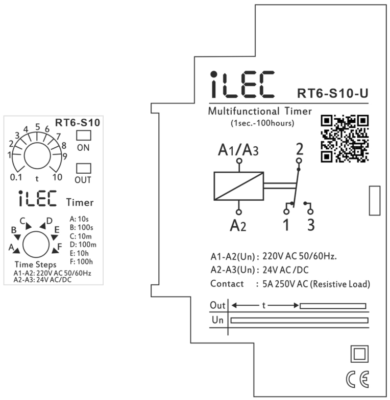
External description
Resources & Support
- Technical documents: Model RT6-S10-U
- Reference Articles: Operating Principles & Practical Applications
- Pricing & Ordering: View Details
Review Relay iLEC RT6-S10-U
STAR DELTA RELAY
Model RT6-SD30-U
Introduction
Star Delta Relay is designed to controll three motors in the first run.

Specifications
| PARAMETER | VALUE |
| Operating voltage (Un) | AC 160V–260V (A1-A2); 24V AC/DC (A1-A3) |
| Operating frequency | 50/60Hz |
| Operating power | <6VA |
| Operating temperature | -20ºC ~ 55ºC |
| Working (star) | 0.1sec. – 30sec. |
| Waiting (off) | 1msec. – 500msec. |
| Display | On led, star led and delta led |
| Connection type | Terminal connection |
| Weight | Max. 110 gr. |
| Contact | 5A/250V AC (Resister Load) |
| Mounting | Assembled on the DIN rail |
| Operating Altitude | <2000m |
| Cable diameter | 2.5 mm² |
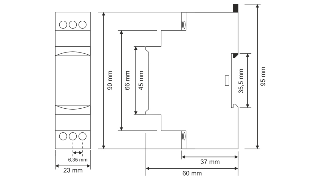
Dimension
Usage of Device and Working Principle
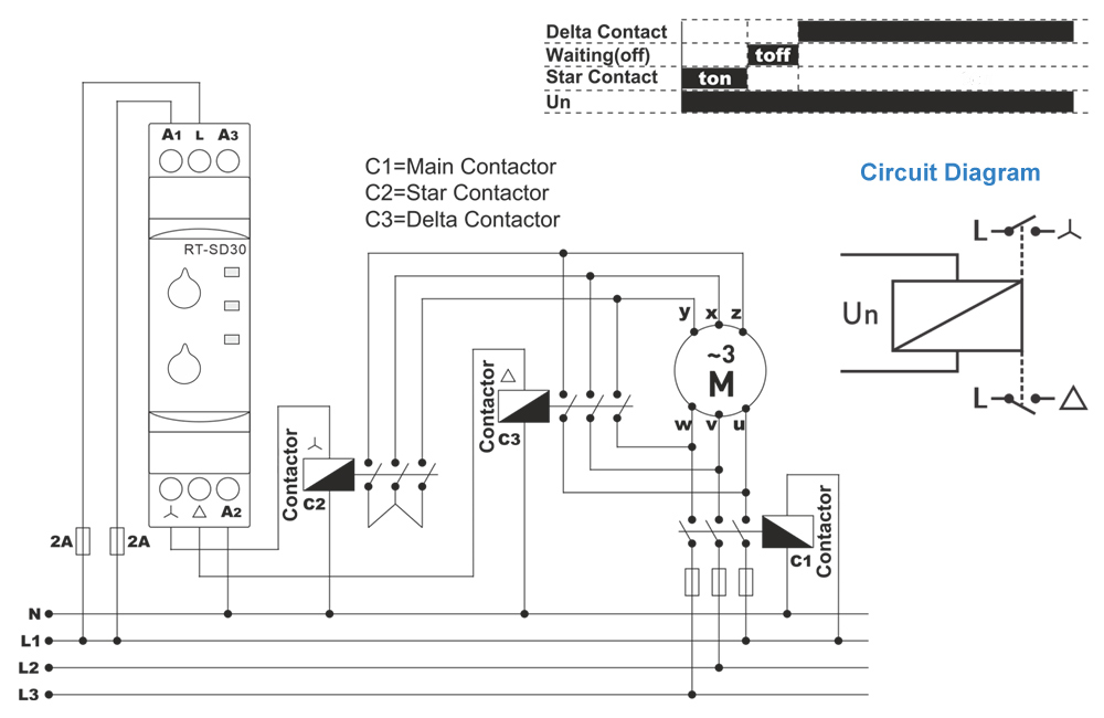
- Make the connections according to the diagram.
- Max.Time (Time Steps, TS ): Adjusts the stage and display the max.time.
- [ t ]: Divides the stage by 10 and multiply with displaying value.
* Example: Time is 75 minutes. - Make stage button to 100m (100 minutes) and turn “t” button between 7-8. In this case time is adjusted to 75 minutes.
* Note: In order to adjust much sensitive higher time values, set “t” by chronometer in low stages and in crease the stage to the time required.
* Example: Time is 25 hours. - Turn stage button to 10s (10 seconds) and “t” button between 2-3. Make power on and check with a chronometer for 2.5 seconds.
- Make the stage button 100h(100 hours). In this case, you set it more sensitive.
- After setting the time, power on the device. Device will start timing and meanwhile led switches on-off.
When device is timing relay contact 2 shorted to 1.
When the timing finish (set time is up) relay led is switches on stable and contact 2 shorted to 3.
Device keeps stable till the power is off.
Typical Connection Diagram
Maintenance
- Switch off the device and release from connections.
- Clean the trunk of device with a swab.
- Don’t use any conductor or chemical might damage the device.
- Make sure device works after cleaning.
Warnings
- Please use the device according to the manual.
- Don’t use the device in wet.
- Include a switch and circuit breaker in the assembly.
- Put the switch and circuit breaker nearby the device, operator can reach easily.
- Mark the switch and circuit breaker as releasing connection for device.
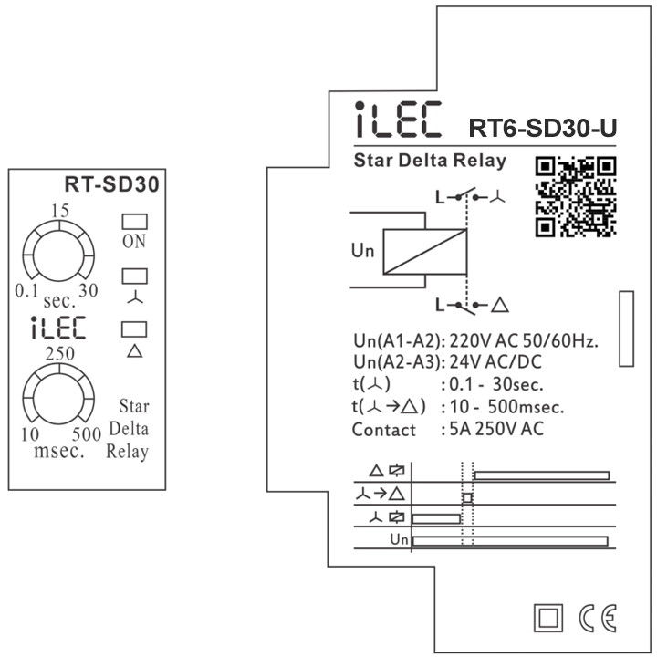
External description
Resources & Support
- Technical documents: Model RT6-SD30-U
- Reference Articles: Star Delta Relay for Induction Motors
- Pricing & Ordering: View Details
Review Relay iLEC RT6-SD30-U
OVER/UNDER VOLTAGE & SEQUENCE RELAY
Model VPR-A2-380/3L
Introduction
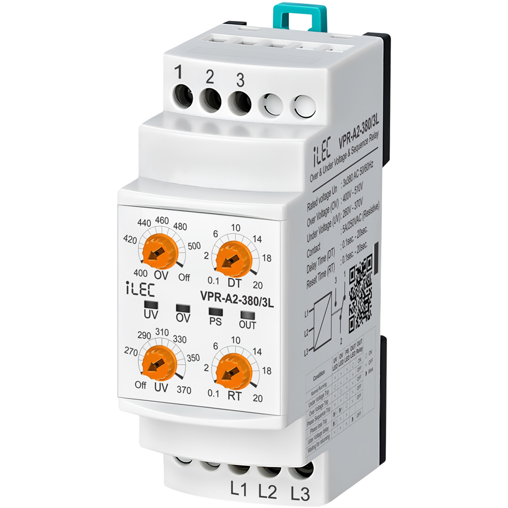
Voltage control relays are designed to protect devices with sensitive operating voltage values from faults that may be caused by mains voltage.
Protection Functions
- Under Voltage Protection - To enter the error state: If one or more of the phases goes below the low voltage set value, the UV LED is on, the device waits until the set delay time (DT), after the time has elapsed the relay gets de-activated and the relay LED is off.
- Under Voltage Protection - Exiting the error state: When all phases goes above by 3% of the low voltage set value, the device waits for the reset time (RT). After the time passes, the UV LED is off, the relay gets activated and the relay LED is on.
- Over Voltage Protection - To enter the error state: If one or more of the phases goes above the high voltage set value, the OV LED is on, the device waits until the set delay time (DT), after the time has elapsed the relay gets deactivated and the relay OUT is off.
- Over Voltage Protection - Exiting the error state: When all phases drops below by 3% of the high voltage set value, the device waits for the reset time (RT). After the time passes, the OV LED is off, the relay gets deactivated and the relay LED is on.
- Phase Sequence Protection: If the phase sequence of the device is reversed, the phase sequence error PS LED will light up and the relay will not gets activated.
- Phase loss or Inadequate Supply Voltage Protection - To enter the error state: UV and OV LEDs flashes when voltage is lower than the nominal operating voltage by 0.4 times, after 100 millisecond the device gets deactivated the relay, and relay LED is turned off.
Specifications
| PARAMETER | VALUE |
| Operating voltage (Un) | 3 x 380V AC, 50/60Hz |
| Over Voltage set | 400V–510V |
| Inder voltage | 260V–370V |
| Delay time | 0.1sec. – 20sec. |
| Reset time | 0.1sec. – 20sec. |
| Operating Power | <6VA |
| Operating temperature | -20ºC ~ 55ºC |
| Display | 4 x LEDs |
| Mounting type | Standard 35mm din ral |
| Weight | 210gr. |
| Contact | 5A 250VAC (Resister Load) |
| Operating Altitude | <2000m |
| Panel hole size | ~ 91 x 91 (mm) |
| Cable size | 2.5mm² |
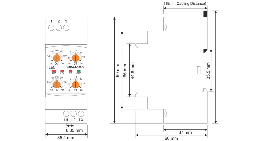
Dimension
Device Usage and Working Principle
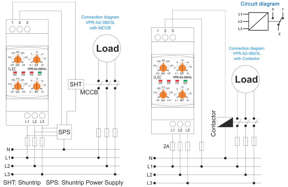
- Make the connections of the device in accordance with connection scheme.
- Set the required settings of the device according to the operating voltage values of the load.
- When the device is energized, if the voltage values are normal according to the set values, the relay gets activated and the relay OUT LED is turned on.
* (In the case of models with phase sequence control, the phase sequence must also be correct.) - When the voltage values go out of the set values, the related fault LED is on, it waits until the delay time (DT), after the time has elapsed, the relay gets deactivated and the relay LED goes out.
- When the voltages return to their normal values, the device waits until the reset time (RT), after the time has elapsed the relay gets activated and the relay LED is turned on.
- The Under Voltage Protection function is deactivated when the The Over Voltage Protection function is deactivated when the OV control knob is set to Off.
- Relay is Deactivated when no power supply or supply with errors 2 and 1 short circuit, 3 and 2 open circuit.
Required Settings and Error Notifications
- UV: Under Voltage Set Value, when the voltage drops below this value, UV LED is on.
- OV: Over Voltage Set Value, when the voltage rises above this value, OV LED is on.
- DT: Delay Time, is the time to wait before entering the fault.
- RT: Reset Time, is the time to wait for the relay to pull when the voltages return to normal.
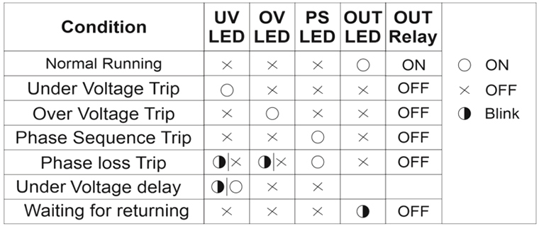
LED Notifications for errors
- UV: Under Voltage Set Value, when the voltage drops below this value, UV LED is on.
- OV: Over Voltage Set Value, when the voltage rises above this value, OV LED is on.
- DT: Delay Time, is the time to wait before entering the fault.
- RT: Reset Time, is the time to wait for the relay to pull when the voltages return to normal.
Maintenance
- Switch off the device and release from connections.
- Clean the trunk of device with a swab.
- Don’t use any conductor or chemical might damage the device.
- Make sure device works after cleaning.
Warnings
- Please use the device according to the manual.
- Don’t use the device in wet.
- Include a switch and circuit breaker in the assembly.
- Put the switch and circuit breaker nearby the device, operator can reach easily.
- Mark the switch and circuit breaker as releasing connection for device.
Typical connection diagram
Resources & Support
- Technical documents: Model VPR-A2-380/3L
- Reference Articles: Voltage Protection Relay for 3-Phase Systems
- Pricing & Ordering: View Details
Review Relay iLEC VPR-A2-380/3L
SMART ENERGY PROTECTION METER
Model SEP-63/1PN
Introduction
- The WIFI Smart Circuit Breaker Protector is designed for AC 50Hz/60Hz circuits with a rated voltage of 220V.
- It enables remote control, multi-user access, and scheduled ON/OFF switching.
- It is suitable for use in homes, schools, factories, municipal projects, street lighting, agricultural motors, water pumps, floor heating systems, water heaters, and other remote intelligent power control applications.
Features
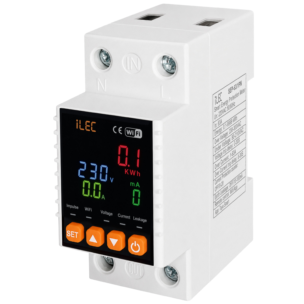
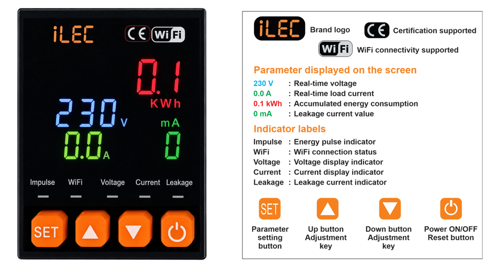
- This product features a backlit LCD display for real-time monitoring of voltage, current, leakage current, and energy consumption.
- It is equipped with a high-precision metering chip 24-bit ADC sampling for accurate measurement.
- It supports adjustable settings for overvoltage, undervoltage, overcurrent, leakage current, and delay time, with cumulative energy monitoring. A one-touch factory reset function is also available.
- When connected to a network, the device supports remote ON/OFF control and real-time monitoring via a mobile app. Parameters such as voltage, current, leakage current, and energy consumption can be monitored in real time.
- Users can configure automatic trip/disconnection functions. Energy statistics can be reset manually or automatically at midnight for daily energy tracking and billing purposes.
- Without requiring additional devices, the unit supports automatic reclosing and provides undervoltage, leakage current, and overcurrent protection.
1. Front-Face Panel
2. Specifications
| PARAMETER | VALUE |
| Rated voltage | AC 220V |
| Rated current | 63A |
| Rated frequency | 50/60Hz |
| Includtive | 6kW (Motor type) |
| Resistive load | 13kW (Electric heating and lighting) |
| Power consumption | <2W |
| Ambient temperature | -250ºC ~ 65C |
| Humidity | <95% |
| Installation method | DIN rail mounting |
| Control mode | Manual / Mobile remote |
| Device setting * Overvoltage setting * Undervoltage setting * Overcurrent setting * Leakage current * Delay setting |
* 30V–300V, adjustable in 1V steps * 110V–210V, adjustable in 1V steps * 1A–63A, adjustable in 1A steps * 10mA–100mA, adjustable in 1mA steps * 1s–999s, adjustable in 1s steps |
| Display accuracy * Volatge * Current * Leakage * Delay setting |
* 1V * 0.1A * 1mA * 0.1kWh |
3. Dimension drawing
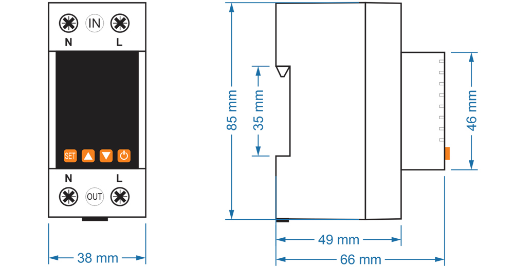
4. Wiring diagram
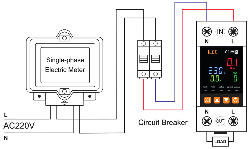
5. Product setting
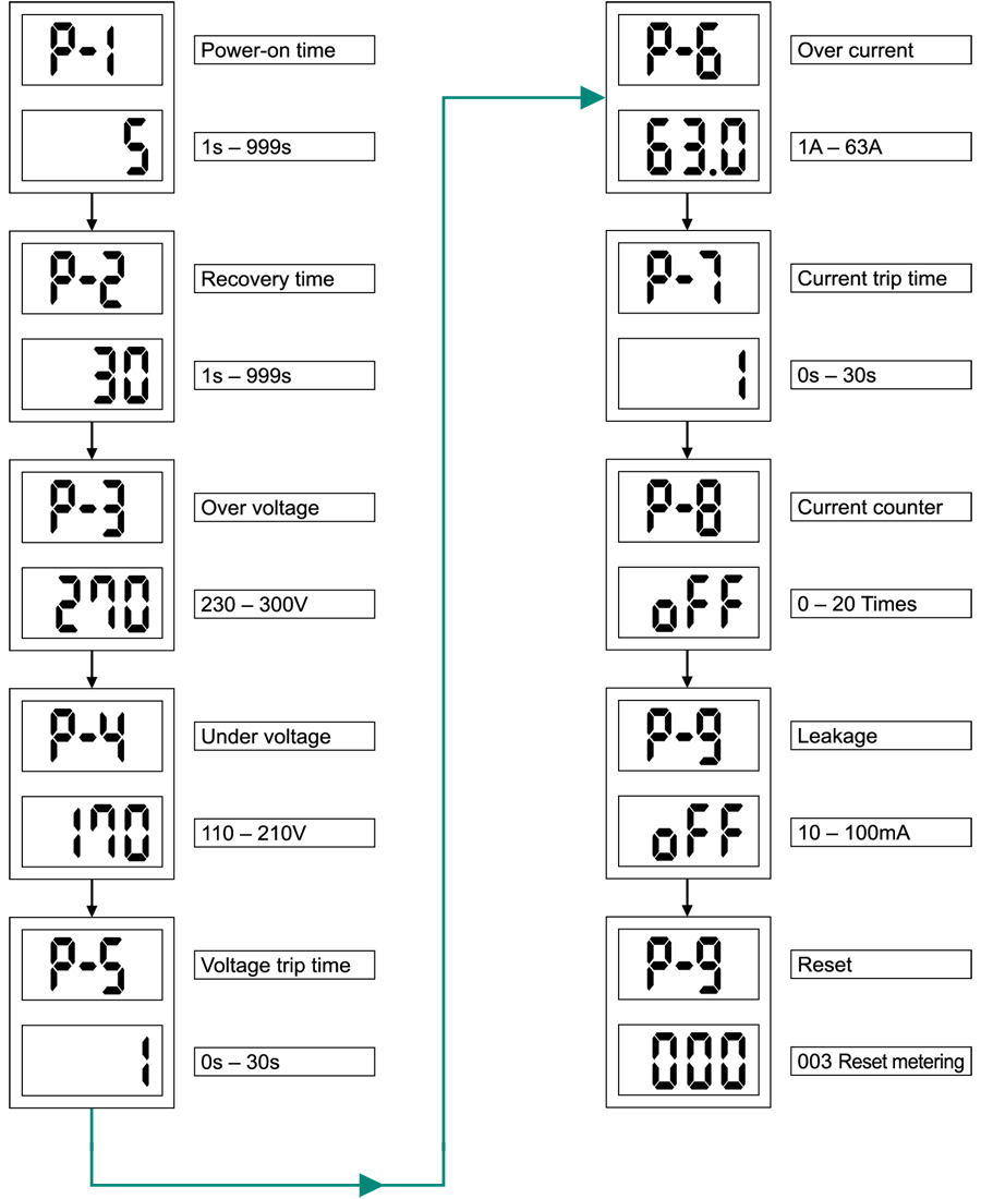
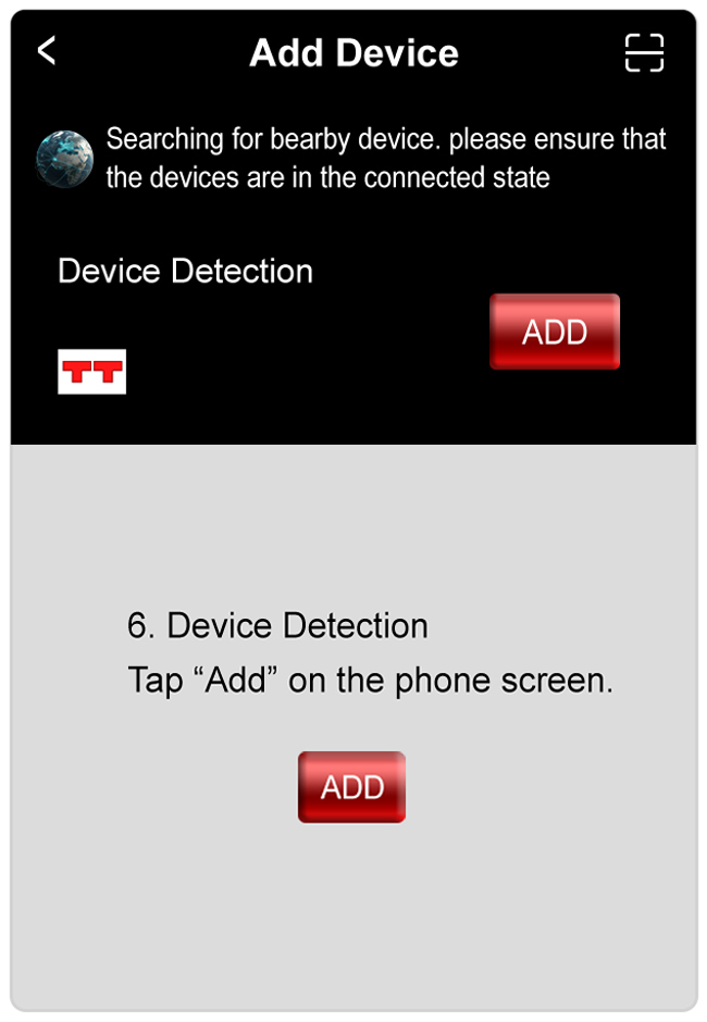
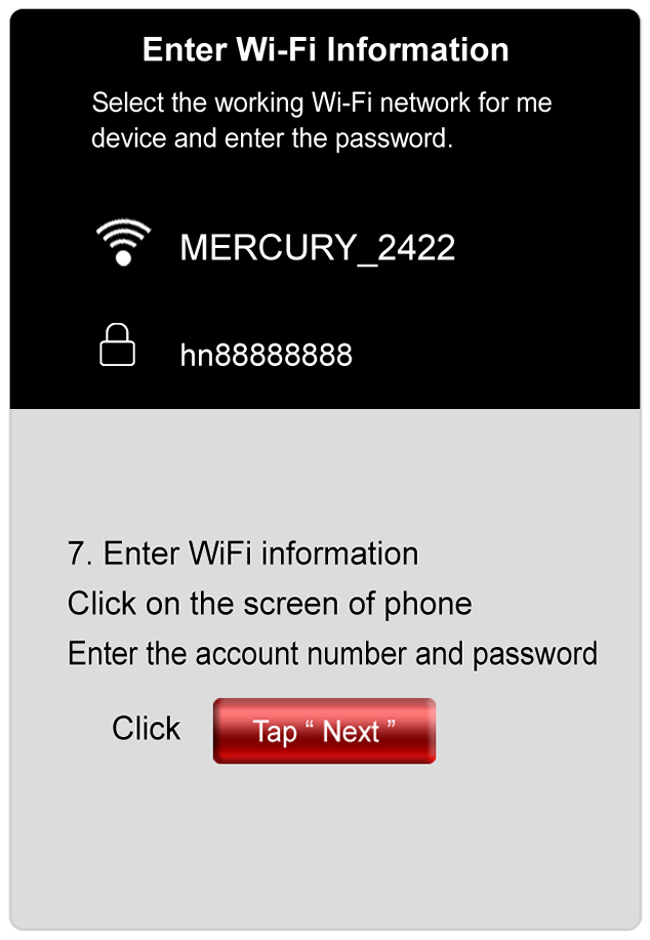
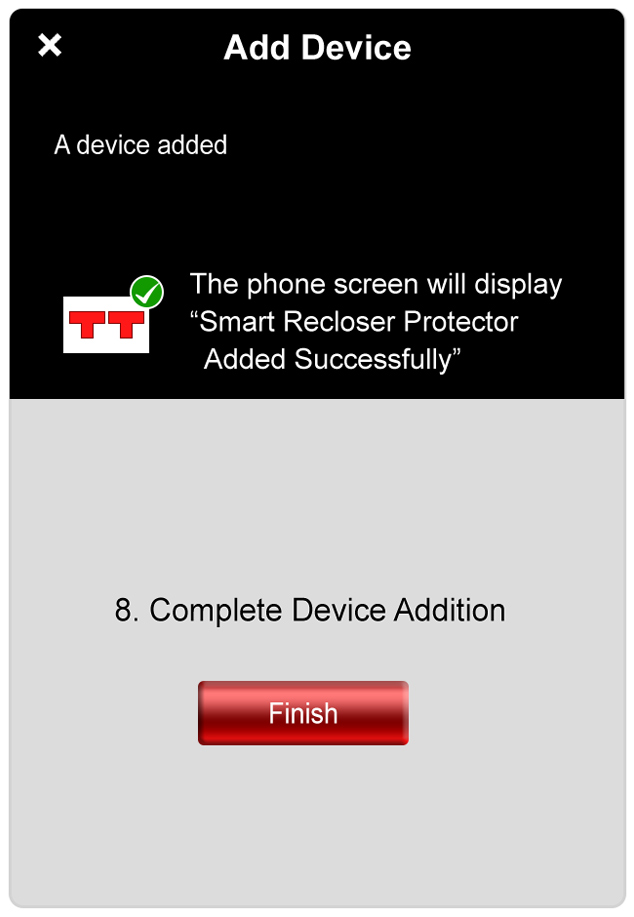
NETWORK OPERATION
Mobile Network Operation Instructions
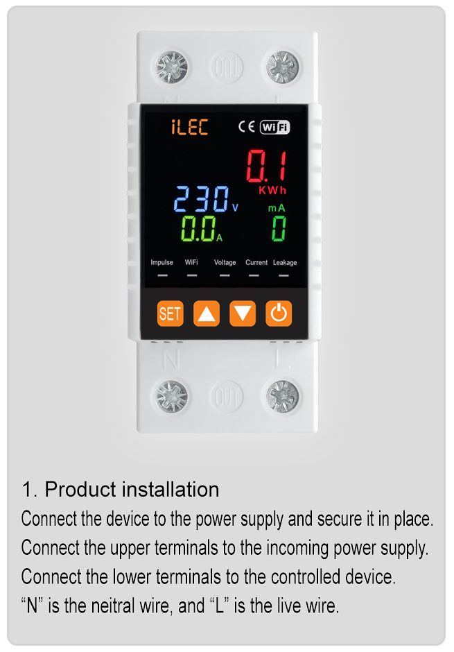
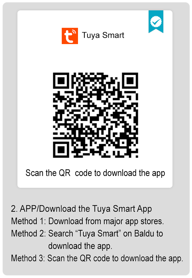
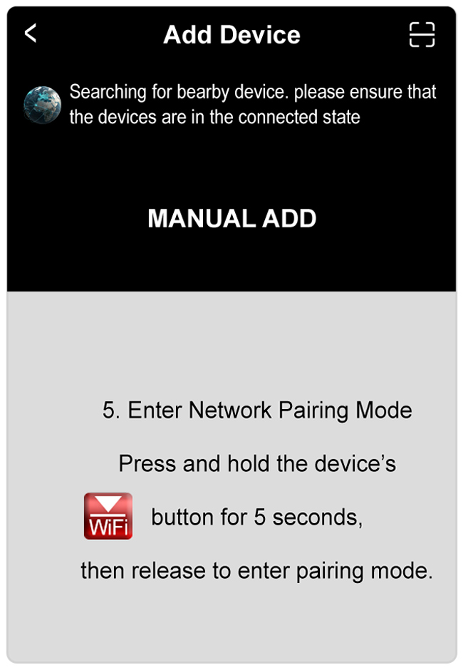
Resources & Support
- User Manual : [ English ] [ Vietnamese ]
- User Guide: Tuya Smart V.3.18.1 – Mobile Network Operation Instructions
- Pricing & Ordering: View Details
VOLTAGE AND CURRENT PROTECTION RELAY
Model VAP-63/3PN
Introduction
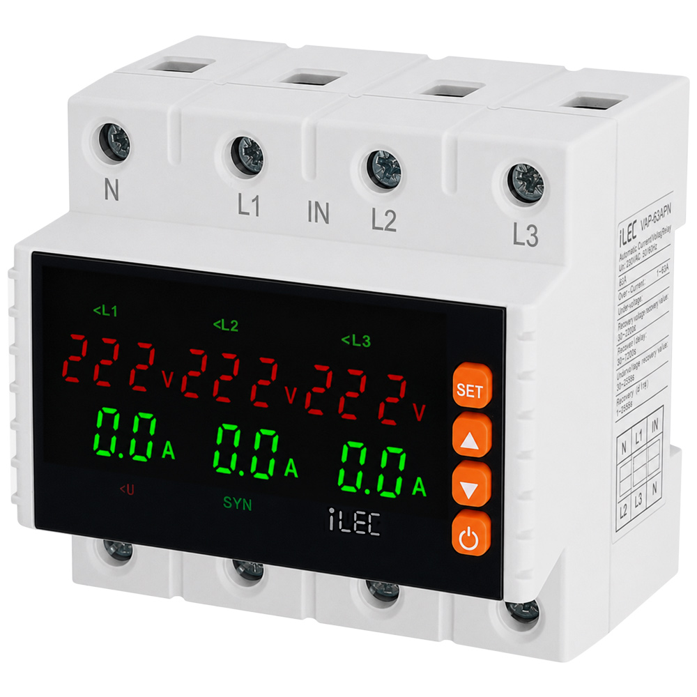
iLEC VAP-63/3PN is a voltage and current protection device for 3P+N 63A system, designed to monitor and protect against overvoltage, undervoltage, overcurrent, phase loss, and phase imbalance conditions. It features automatic switching and automatic recovery after faults.
Features
- Overvoltage, undervoltage, overcurrent, phase loss, and phase imbalance protection to help prevent electrical system failures.
- Compact design with flame-retardant engineering plastic housing, providing excellent insulation and heat resistance.
- DIN rail mounting module, suitable for residential, commercial, and industrial electrical panels.
- LED display for clear real-time monitoring of voltage, current, and operating status.
- Adjustable voltage, current protection thresholds, and recovery delay time.
- Parameters can be easily configured via front-panel function buttons.
- Screw-type terminals ensure fast, secure, and safe wiring connections.
- High-durability conductive alloy relay contacts for stable operation.
- Automatic power cut-off and automatic reconnection when voltage and current return to normal conditions.
- Effectively protects electrical equipment, machinery, control cabinets, and power distribution systems.
Product Characteristics
- Microcontroller-based design for stable and reliable operation.
- Synchronous (SYN) and Asynchronous (ASY) operating modes.
- Voltage measurement accuracy: ±1%.
- 6-module DIN rail mounting design.
Front-Face Panel
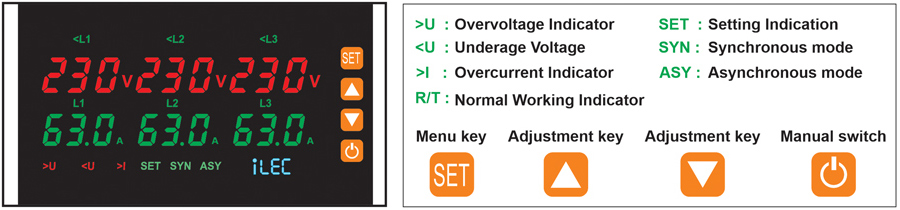
Reset/start delay display:
Voltage operating values display on L1-L2-L3 and current. The current is displayed on the second row, they will be normally ON after the display is over and the output relay closes.
Indication for incorrect phase sequence:
Display L1-L3-L2 when phase failure fault occurs. User can change the position of L2 and L3 after disconnected supply.
Indication of continuous over current faults:
Display for continuous over current faults after reset/start delay is over. Over current faults times is more than preset times. Disconnect the overload device. Start the relay after reset manually.
Specifications
| PARAMETER | VALUE |
| Rated supply voltage | AC 230 |
| Rated supply voltage | AC 80V – 300V |
| Rated frequency | 50/60Hz |
| Hysteresis | Overvoltage & asymmetry: 5V – Undervoltage: 5V |
| Max. operating current | 63A |
| Asymmetry trip delay | 10s |
| Voltage measurement accuracy | 1% (over the whole range) |
| Rated insulation voltage | 450V |
| Output contact | 1NO |
| Electrical life | 105 |
| Mechanical life | 105 |
| Protection degree | IP20 |
| Pollution degree | 3 |
| Altitude | <2000m |
| Operating temperature | -5ºC ~ 40ºC |
| Humidity | ≤50% at 40º C (without condensation) |
| Storage temperature | -25ºC ~ 55ºC |
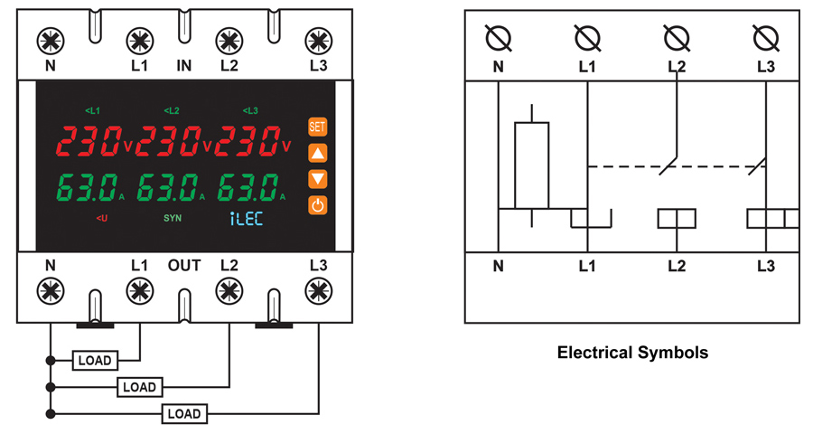
Wiring Diagram
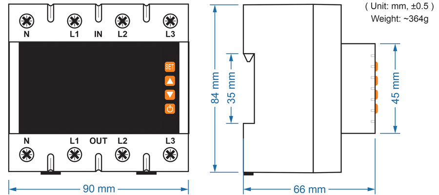
Dimension
Operating Instructions
▪ Voltage Fault Detection
If a voltage fault is detected during the relay reset/start delay countdown, the output relay will disconnect and the fault indication LED will light up.
▪ Normal Operation
During normal operation, the display shows real-time voltage and current values. If a voltage or current fault is detected, the output relay disconnects and the fault indication LEDs light up.
▪ Voltage Fault Recovery
When the input voltage returns to the hysteresis threshold (Hys) after a voltage fault trip, the relay resets automatically.
During the reset/start delay countdown, the fault indication LEDs turn off and the operating voltage and current values flash on the display.
▪ Current Fault Recovery
After the relay trips due to an overcurrent fault, it resets automatically.
During the reset/start delay countdown, the fault indication LED turns off and the operating voltage and current values flash on the display.
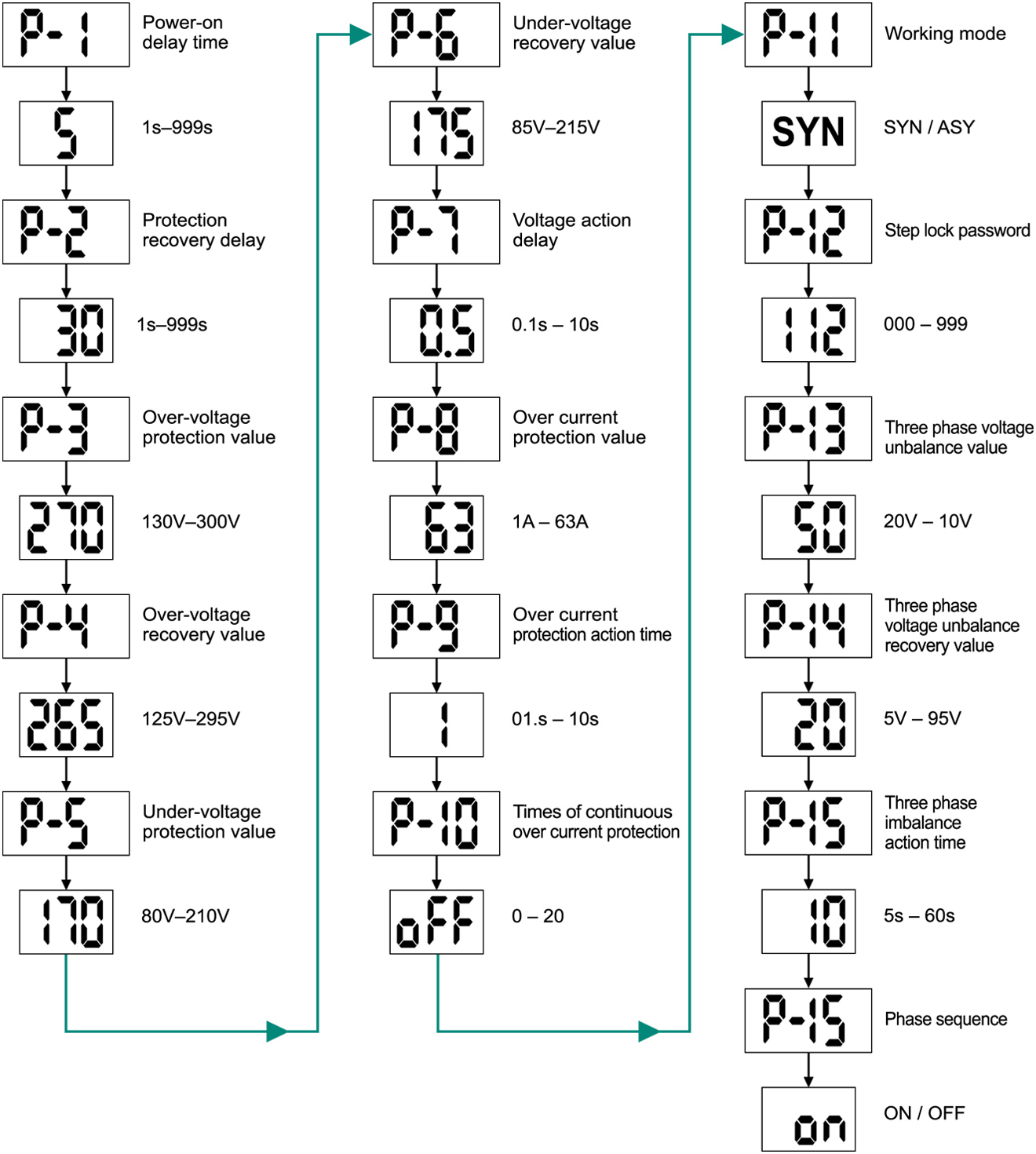
Setting Menu
Resources & Support
- User Manual: Protection Relay [ English ] [Vietnamese]
- Pricing & Ordering: View Details
AUTOMATIC VOLTAGE AND CURRENT PROTECTION RELAY
Model VAP-63/1PN
Introduction
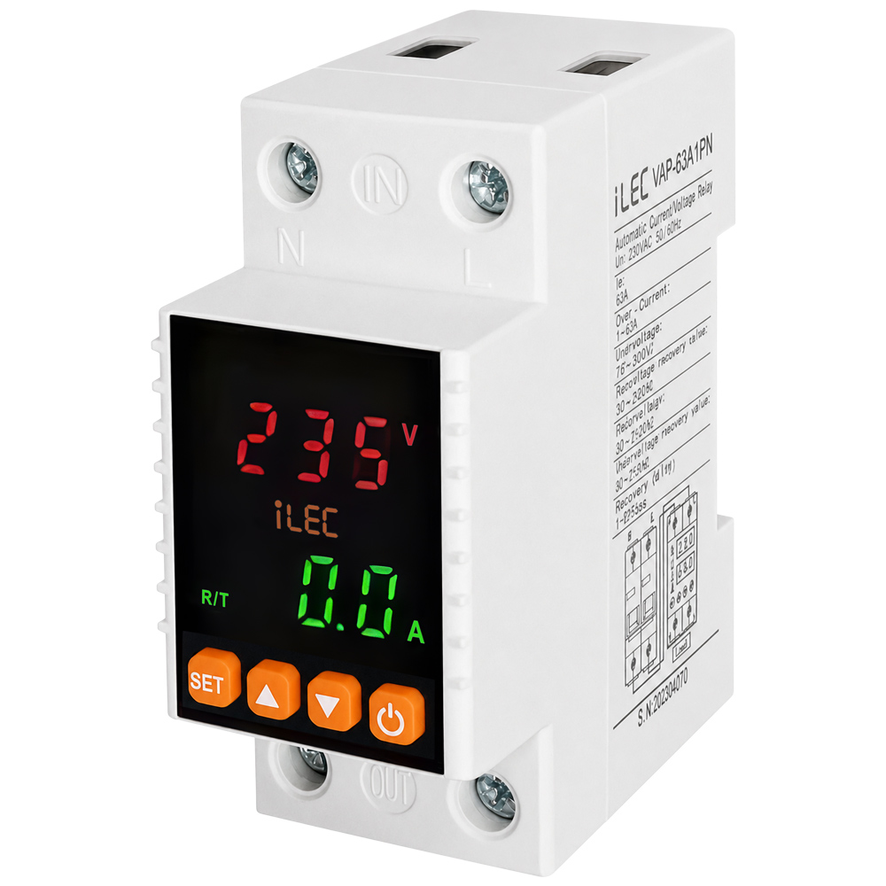
iLEC VAP-63A/1PN is a voltage and current protection device for 1P+N 63A systems, designed to monitor and protect against overvoltage, undervoltage, and overcurrent conditions. It features automatic switching and automatic recovery after faults.
Features
- Overvoltage, undervoltage, and overcurrent protection to help prevent electrical overload.
- Compact design with flame-retardant engineering plastic housing, providing excellent insulation and heat resistance.
- DIN rail mounting module, suitable for residential and industrial electrical panels.
- LED display for clear real-time monitoring of voltage, current, and operating status.
- Adjustable voltage, current protection thresholds, and recovery delay time.
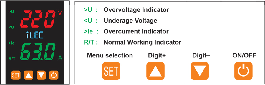
- Parameters can be easily configured via front-panel function buttons.
- Screw-type terminals ensure fast, secure, and safe wiring connections.
- High-durability conductive alloy relay contacts for stable operation.
- Automatic power cut-off and automatic reconnection when voltage returns to normal.
- Effectively protects household appliances, machinery, electrical cabinets, and power systems.
- Suitable for homes, offices, shops, and small industrial workshops.
Front-Face Panel
Specifications
| PARAMETER | VALUE |
| Supply terminal | N, L |
| Rated supply voltage | AC 220V |
| Rated frequency | 50/60Hz |
| Overvoltage protection setting range | 130 – 300V |
| Undervoltage protection setting range | 80 – 210V |
| Voltage hysteresis | 5V |
| Overvoltage trip delay | 0.5s |
| Voltage accuracy | <1% |
| Max. operating phase voltage | 350V |
| Max. operating current | 63A |
| Altitude | ≤2000m |
| Ambient temperature | -25ºC ~ 50ºC |
| Permissible relative humidity | ≤50% at 40ºC (without condensation) |
| Storage temperature | -25ºC ~ 55ºC |
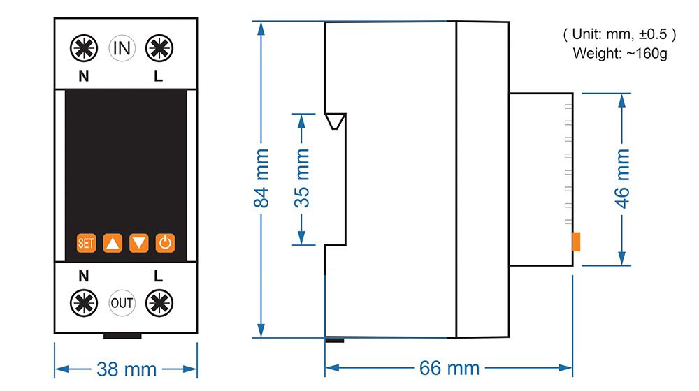
Dimension
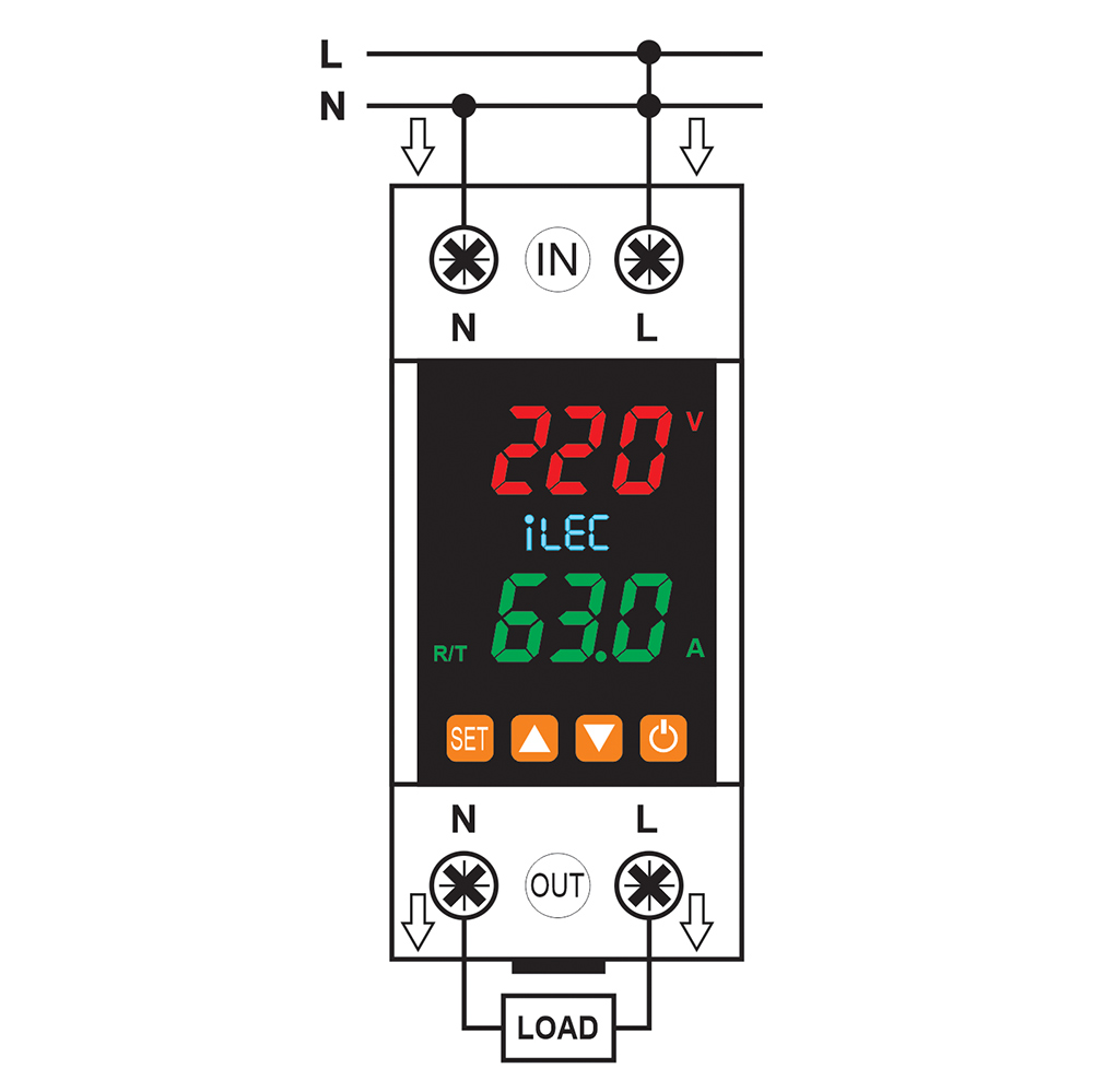
Wiring diagram
Resources & Support
- User Manual: Protection Relay [ English ] [Vietnamese]
- Pricing & Ordering: View Details