
OVER/UNDER VOLTAGE & SEQUENCE RELAY
Model VPR-A2-380/3L
IntroductionVoltage control relays are designed to protect devices with sensitive operating voltage values from faults that may be caused by mains voltage. |
 |
Protection Functions
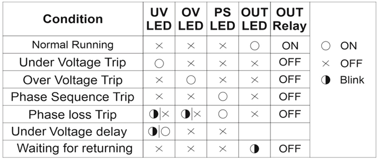
- Under Voltage Protection - To enter the error state: If one or more of the phases goes below the low voltage set value, the UV LED is on, the device waits until the set delay time (DT), after the time has elapsed the relay gets de-activated and the relay LED is off.
- Under Voltage Protection - Exiting the error state: When all phases goes above by 3% of the low voltage set value, the device waits for the reset time (RT). After the time passes, the UV LED is off, the relay gets activated and the relay LED is on.
- Over Voltage Protection - To enter the error state: If one or more of the phases goes above the high voltage set value, the OV LED is on, the device waits until the set delay time (DT), after the time has elapsed the relay gets deactivated and the relay OUT is off.
- Over Voltage Protection - Exiting the error state: When all phases drops below by 3% of the high voltage set value, the device waits for the reset time (RT). After the time passes, the OV LED is off, the relay gets deactivated and the relay LED is on.
- Phase Sequence Protection: If the phase sequence of the device is reversed, the phase sequence error PS LED will light up and the relay will not gets activated.
- Phase loss or Inadequate Supply Voltage Protection - To enter the error state: UV and OV LEDs flashes when voltage is lower than the nominal operating voltage by 0.4 times, after 100 millisecond the device gets deactivated the relay, and relay LED is turned off.
Specifications
| PARAMETER | VALUE |
| Operating voltage (Un) | 3 x 380V AC, 50/60Hz |
| Over Voltage set | 400V–510V |
| Inder voltage | 260V–370V |
| Delay time | 0.1sec. – 20sec. |
| Reset time | 0.1sec. – 20sec. |
| Operating Power | < 6VA |
| Operating temperature | -20ºC ~ 55ºC |
| Display | 4 x LEDs |
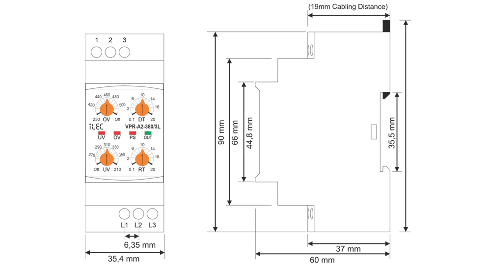
| Mounting type | Standard 35mm din ral |
| Weight | 210gr. |
| Contact | 5A 250VAC (Resister Load) |
| Operating Altitude | < 2000m |
| Panel hole size | < 91 x 91 (mm) |
| Cable size | 2.5mm² |
Dimension
Device Usage and Working Principle
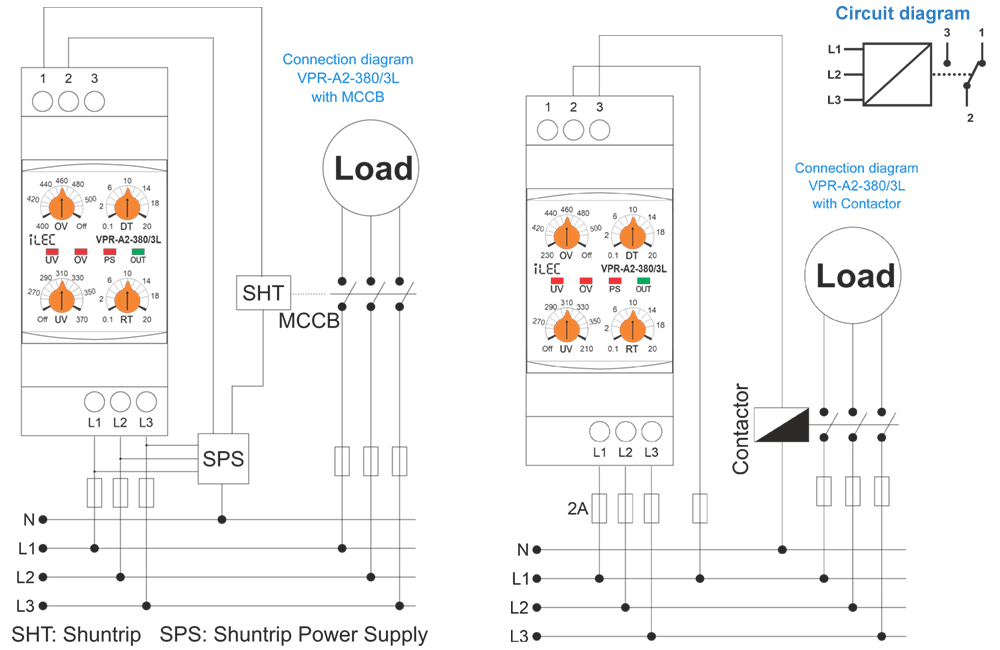
- Make the connections of the device in accordance with connection scheme.
- Set the required settings of the device according to the operating voltage values of the load.
- When the device is energized, if the voltage values are normal according to the set values, the relay gets activated and the relay OUT LED is turned on.
- When the voltage values go out of the set values, the related fault LED is on, it waits until the delay time (DT), after the time has elapsed,
- When the voltages return to their normal values, the device waits until the reset time (RT), after the time has elapsed the relay gets activated and the relay LED is turned on.
- The Under Voltage Protection function is deactivated when the The Over Voltage Protection function is deactivated when the OV control knob is set to Off.
- Relay is Deactivated when no power supply or supply with errors 2 and 1 short circuit, 3 and 2 open circuit.
* (In the case of models with phase sequence control, the phase sequence must also be correct.)
the relay gets deactivated and the relay LED goes out.
Required Settings and Error Notifications
- UV: Under Voltage Set Value, when the voltage drops below this value, UV LED is on.
- OV: Over Voltage Set Value, when the voltage rises above this value, OV LED is on.
- DT: Delay Time, is the time to wait before entering the fault.
- RT: Reset Time, is the time to wait for the relay to pull when the voltages return to normal.
LED Notifications for errors
- UV: Under Voltage Set Value, when the voltage drops below this value, UV LED is on.
- OV: Over Voltage Set Value, when the voltage rises above this value, OV LED is on.
- DT: Delay Time, is the time to wait before entering the fault.
- RT: Reset Time, is the time to wait for the relay to pull when the voltages return to normal.
Maintenance
- Switch off the device and release from connections.
- Clean the trunk of device with a swab.
- Don’t use any conductor or chemical might damage the device.
- Make sure device works after cleaning.
Warnings
- Please use the device according to the manual.
- Don’t use the device in wet.
- Include a switch and circuit breaker in the assembly.
- Put the switch and circuit breaker nearby the device, operator can reach easily.
- Mark the switch and circuit breaker as releasing connection for device.
Typical connection diagram
Resources & Support
- Technical documents: Model VPR-A2-380/3L
- Reference Articles: Voltage Protection Relay for 3-Phase Systems
- Pricing & Ordering: Please visit !
