
INTERMEDIATE RELAY
Introduction
An intermediate relay is an electromagnetic switch that acts as a buffer between a low-power control circuit and a high-power load circuit. It is used to amplify signals, isolate circuits, and split control signals into multiple outputs.
Main Functions:
- Signal amplification: Allows small current/voltage signals (e.g., from PLCs or sensors) to directly control heavy load devices like motors or lighting systems.
- Electrical isolation: Ensures safety by protecting the central controller from overcurrent and overvoltage issues in the load circuit.
- Contact multiplication: From a single input signal, the relay can activate multiple contacts (usually 4 to 8) to control several components simultaneously.
Structure & Classification:
- Structure: Consists of an electromagnetic coil, a contact system (Normally Closed NC / Normally Open NO), a spring, and a protective housing.
- Classification: Categorized by specifications such as voltage (5V, 12V, 24V DC, 220V AC...) or the number of pins (5 pins, 8 pins, 11 pins, 14 pins).
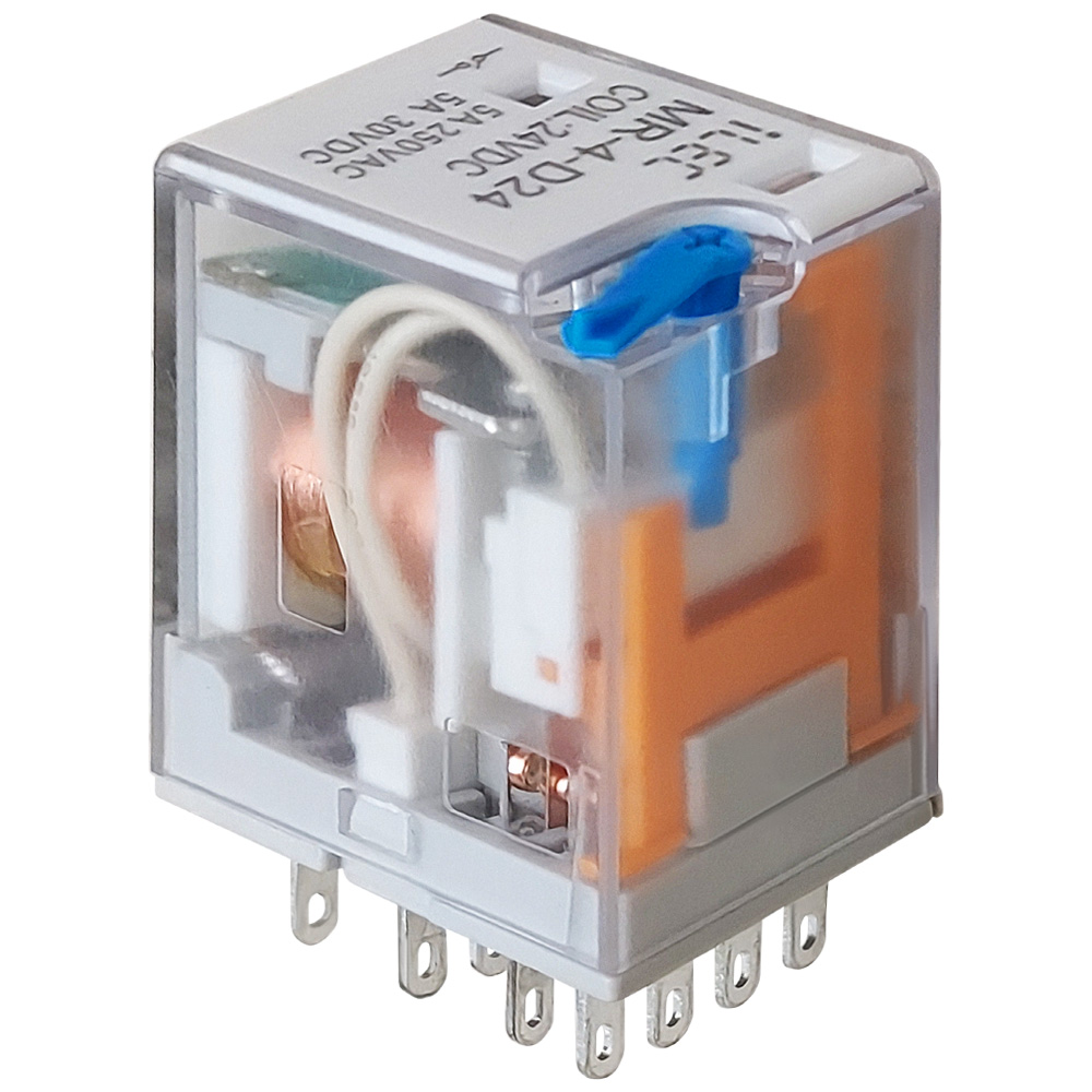
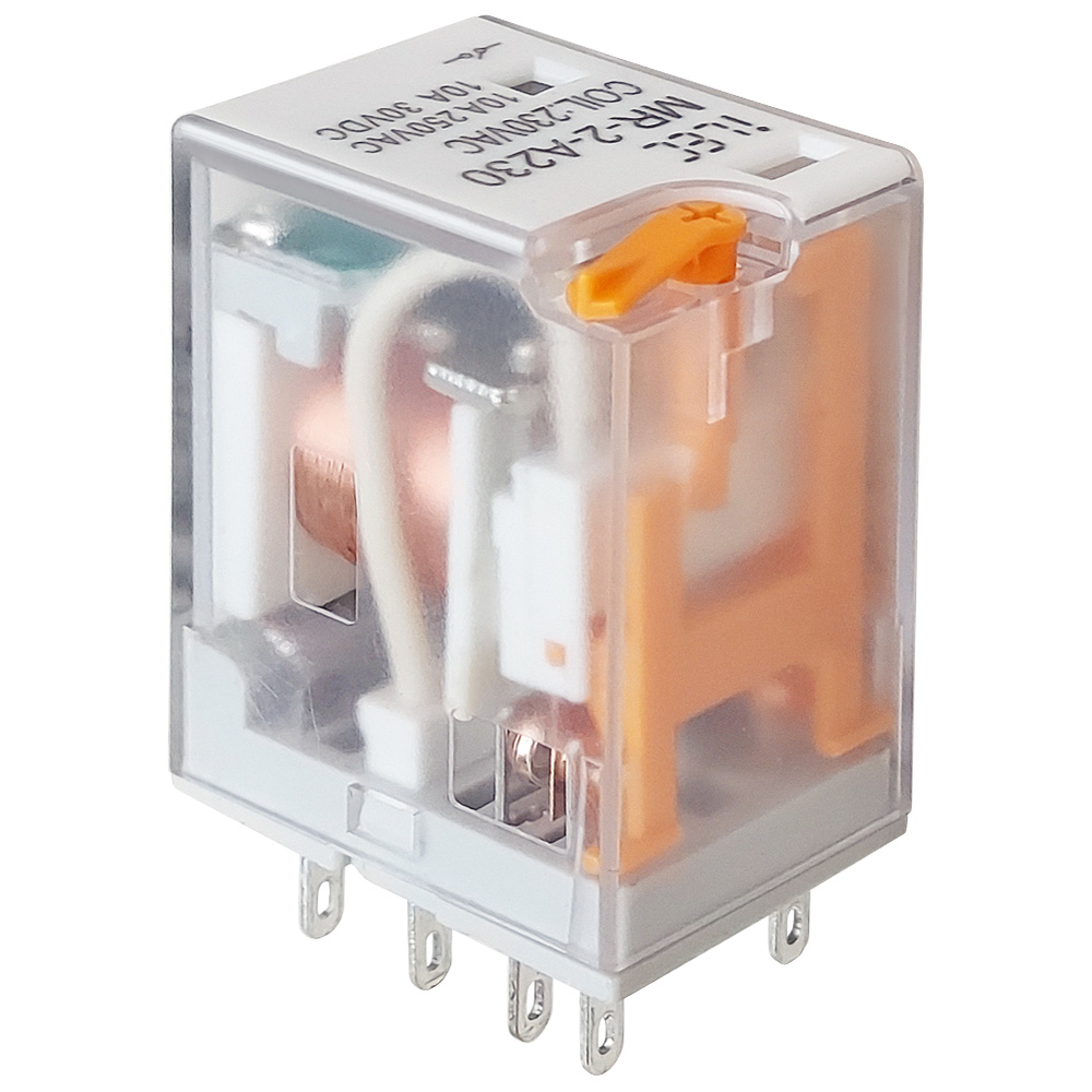
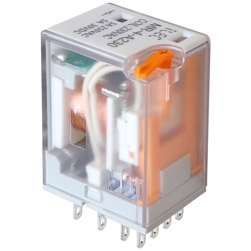
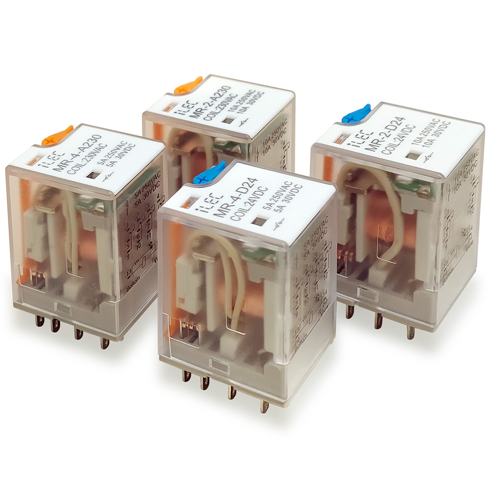
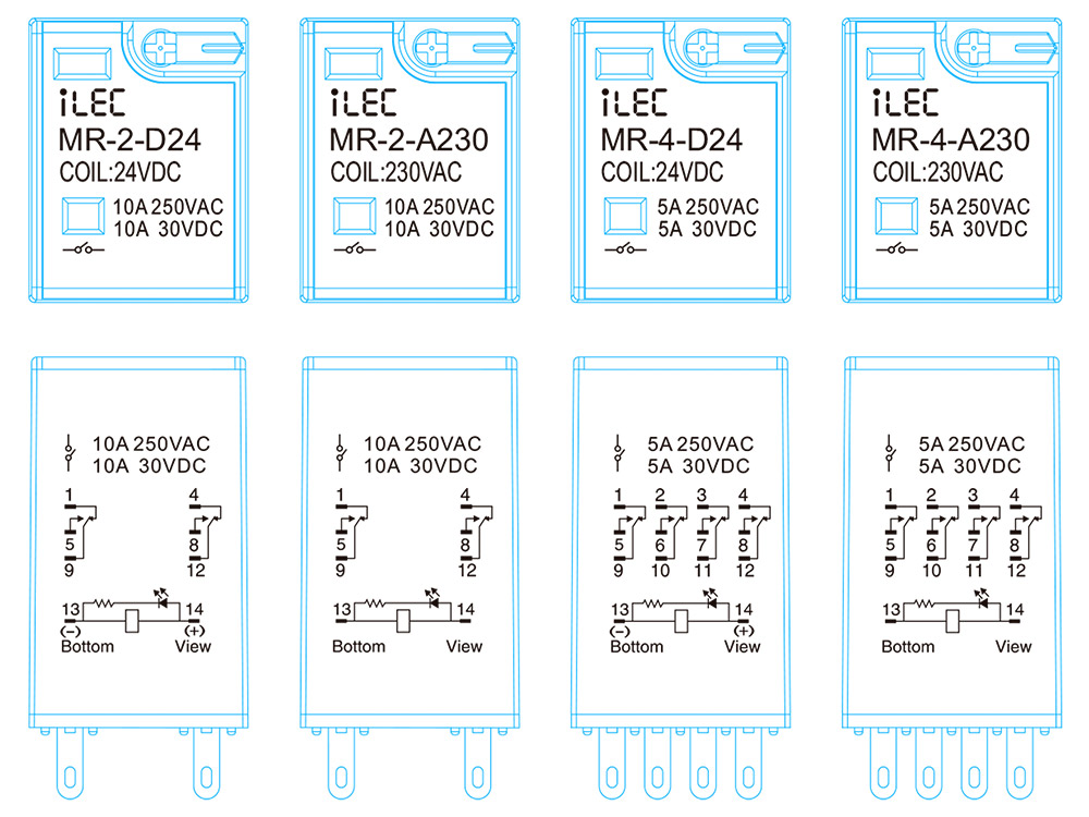
iLEC Intermediate Relay – Model MR
Features
- Compact and durable construction with high dielectric strength.
- Transparent cover for clear visibility of internal operations.
- Manual test button with locking clip for convenient maintenance (Green: DC, Orange: AC).
- Clear mechanical and LED status indicators.
- Terminal layout printed directly on the case for easy wiring.
- DIN rail or panel mounting options.
Applications
- Industrial control panels.
- PLC intermediate control & status monitoring circuits.
- Control of lights, fans, motors, contactors, and solenoid valves.
General Characteristics |
|
| Type | Electromagnetic intermediate relay |
| Terminal type | Contact meterial |
| Contact resister | < 50mΩ |
| Operate/Release time | < 20ms |
| Insulation resister | ≥ 500mΩ (500VDC) |
| Electrical/Mechanical life | ≥ 100.000 times / 10.000.000 times |
| Operating temperature | -25ºC ~ 55ºC |
| Humidity | 35~85% RH |
| Atmospheric pressure | 86~106 KPa |
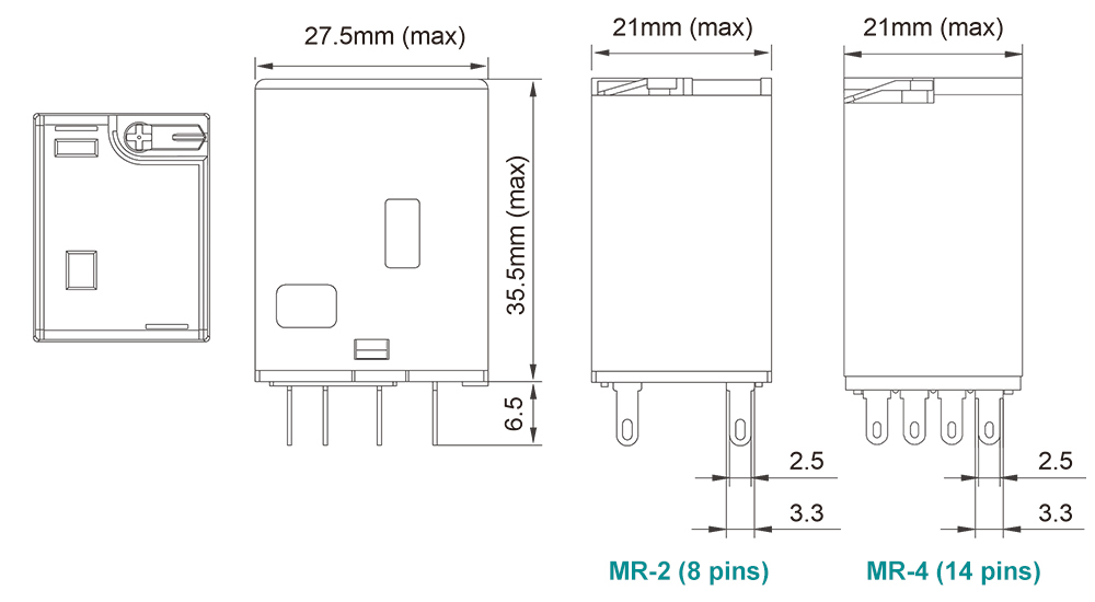
| Dimension (WxHXD) | 21 x 42.5 x 27 (mm) |
| Weight | 32~3g |
| Suitable socket | Model PYF |
Technical Data |
||||
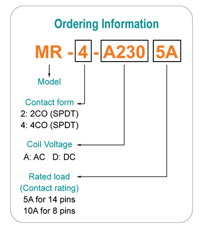
| Model | MR-2-A230 | MR-4-A230 | MR-2-D24 | MR-4-D24 |
| Number of pins | 8 pins | 14 pins | 8 pins | 14 pins |
| Coil voltage | 230VAC | 230VAC | 24VDC | 24VDC |
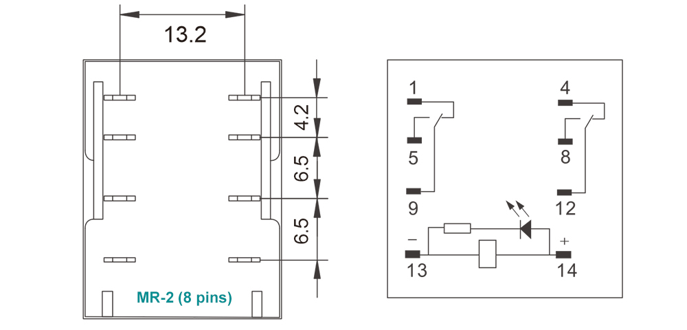
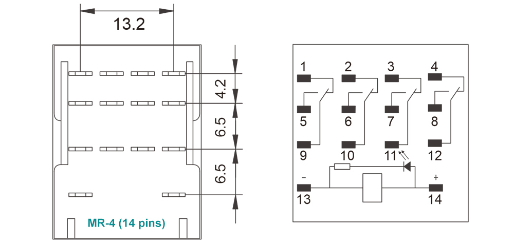
| Contact configuration | 2NO+2NC | 4NO+4NC | 2NO+2NC | 4NO+4NC |
| Contact rating | 10A | 5A | 10A | 5A |
DC Coil Data |
|||
| Rated Voltage VDC | Pickup Voltage VDC | Dropout Voltage VDC | Coil Resistance Ω±10% |
| 5 | 4.0 | 0.5 | 0.5 |
| 6 | 4.8 | 0.6 | 0.6 |
| 12 | 9.6 | 1.2 | 1.2 |
| 24 | 19.2 | 2.4 | 2.4 |
| 48 | 38.4 | 4.8 | 4.8 |
| 110 | 88.0 | 11.0 | 11.0 |
AC Coil Data |
|||
| Rated Voltage VDC | Pickup Voltage VDC | Dropout Voltage VDC | Coil Resistance Ω±10% |
| 6 | 4.80 | 1.80 | 10.5 |
| 12 | 9.60 | 3.60 | 46.5 |
| 24 | 19.2 | 7.20 | 192 |
| 48 | 38.4 | 14.4 | 783 |
| 110 / 120 | 88.0 | 38.0 | 4000 |
| 220 / 240 | 176.0 | 66.0 | 15000 |
Dimensions
Wiring diagrams
Product marking
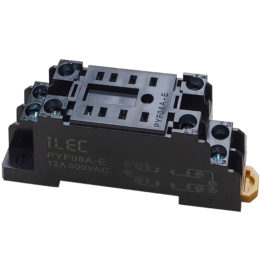
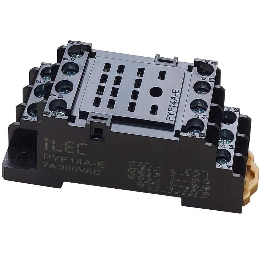
iLEC PYF Series Sockets
Product Appearance
- Compact design with high-strength, insulated, and flame-retardant engineering plastic.
- Dual-side screw terminal wiring for effortless relay replacement.
- DIN rail and screw mounting support for convenient wiring and panel maintenance.
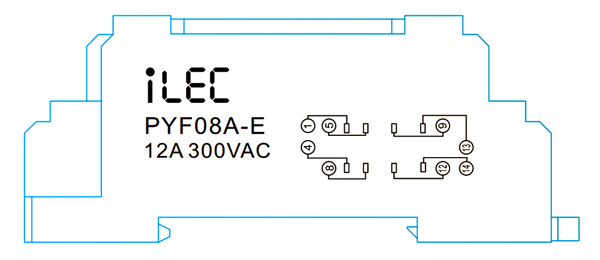
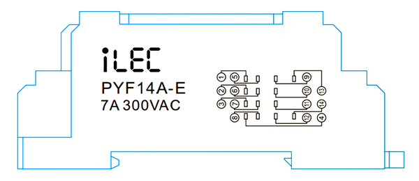
- Terminal layout printed directly on the housing for fast and accurate wiring.
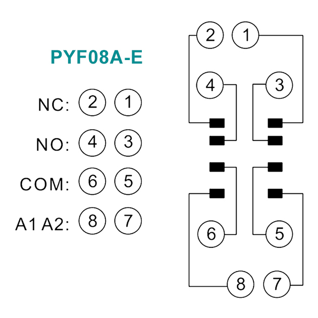
- PYF08A-E is compatible with MR-2 and standard 8-pin intermediate relays.
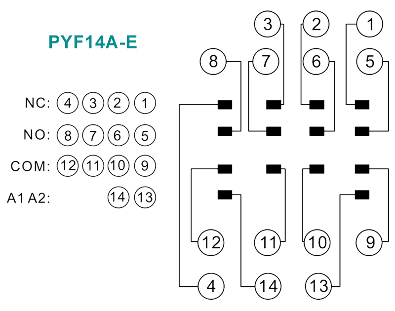
- PYF14A-E is compatible with MR-4 and standard 14-pin intermediate relays.
| Model | PYF08A-E | PYF14A-E |
| Number of Positions | 8 pins | 14 pins |
| Load Current/Voltage | 12A 300VAC | 7A 300VAC |
| Dielectric Strength Voltage | 2kV | 2kV |
| Wire size (AWG/mm²) | 20-16/0.5-1.5 | 20-16/0.5-1.5 |
| Tightening Torque (Nn) | 0.7 | 0.7 |
| Terminal Ingress Protection | IP20 | IP20 |
| Compatible Relay | MR-2 series relays | MR-4 series relays |
| Product size | 22 x 75.5 x 31 (mm) | 29 x 75.5 x 31 (mm) |
| Mounting hole pitch | 15 x 59 (mm) | 22 x 59 (mm) |
| Screw Size | 2 x M4~M10 | 2 x M4~M10 |
| Weight | 33g | 52g |
Dimensions
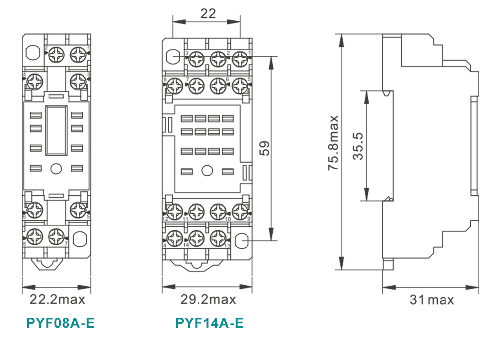
Connection diagrams