

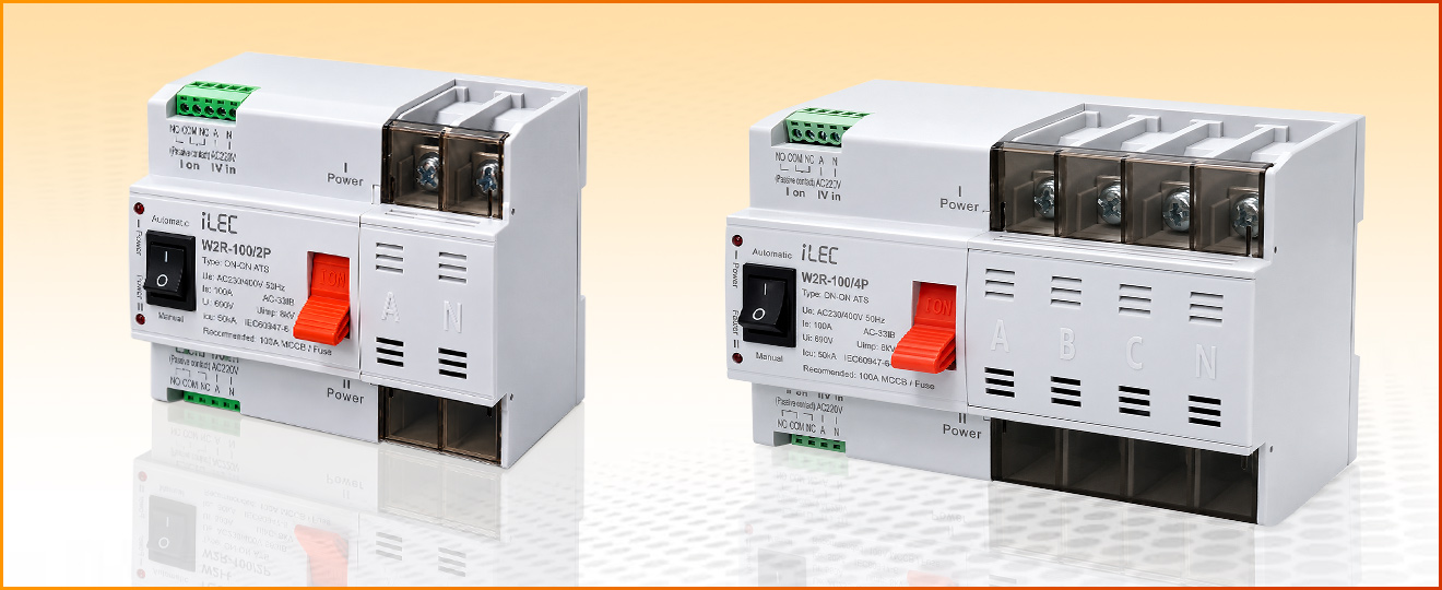
Dual Power Automatic Transfer Switch
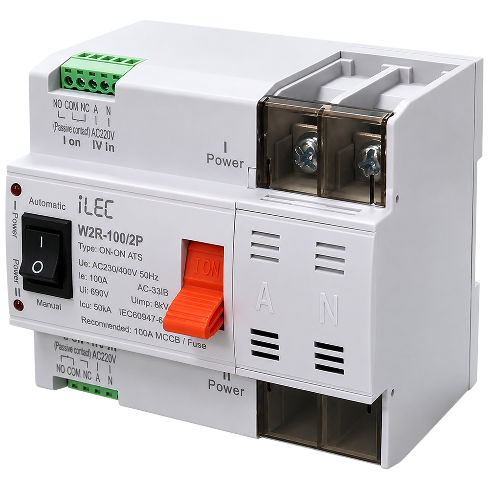
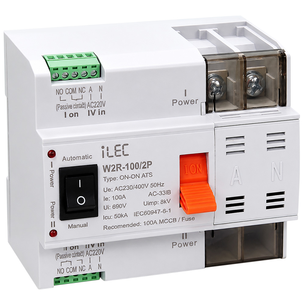
W2R-100/2P
General
ATS dual power switch (hereinafter referred to as “Switch”) is a switch that can continue to supply power in case of emergency. The switch consists of a load switch and a controller, which is mainly used to detect whether the main power supply or standby power supply is normal. When the main power supply is abnormal, the standby power supply will start to work immediately, so as to ensure the continuity, reliability and safety of power supply. This product is specially designed for household guide rail installation and is specially used for PZ30 distribution box.
This switch is suitable for emergency power supply systems with 50Hz/60Hz, rated voltage of 400V and rated current of less than 100A. It is widely used in various occasions where power outages cannot be sustained. (The main and standby power supply can be the power grid, or start the generator set, storage battery, etc. The main and standby power supply is customized by the user).
The product complies with the IEC 60947-6-1 and IEC 60947-3 standards for low-voltage switchgear and controlgear: functional equipment and transfer switch equipment
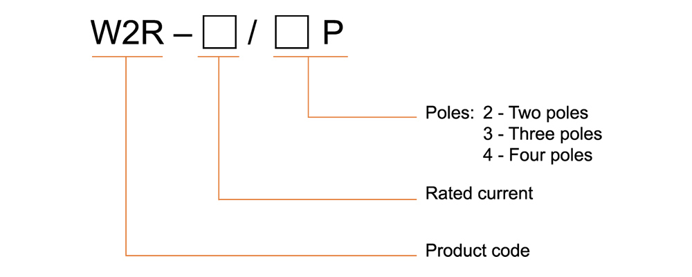
Ordering Code Structure
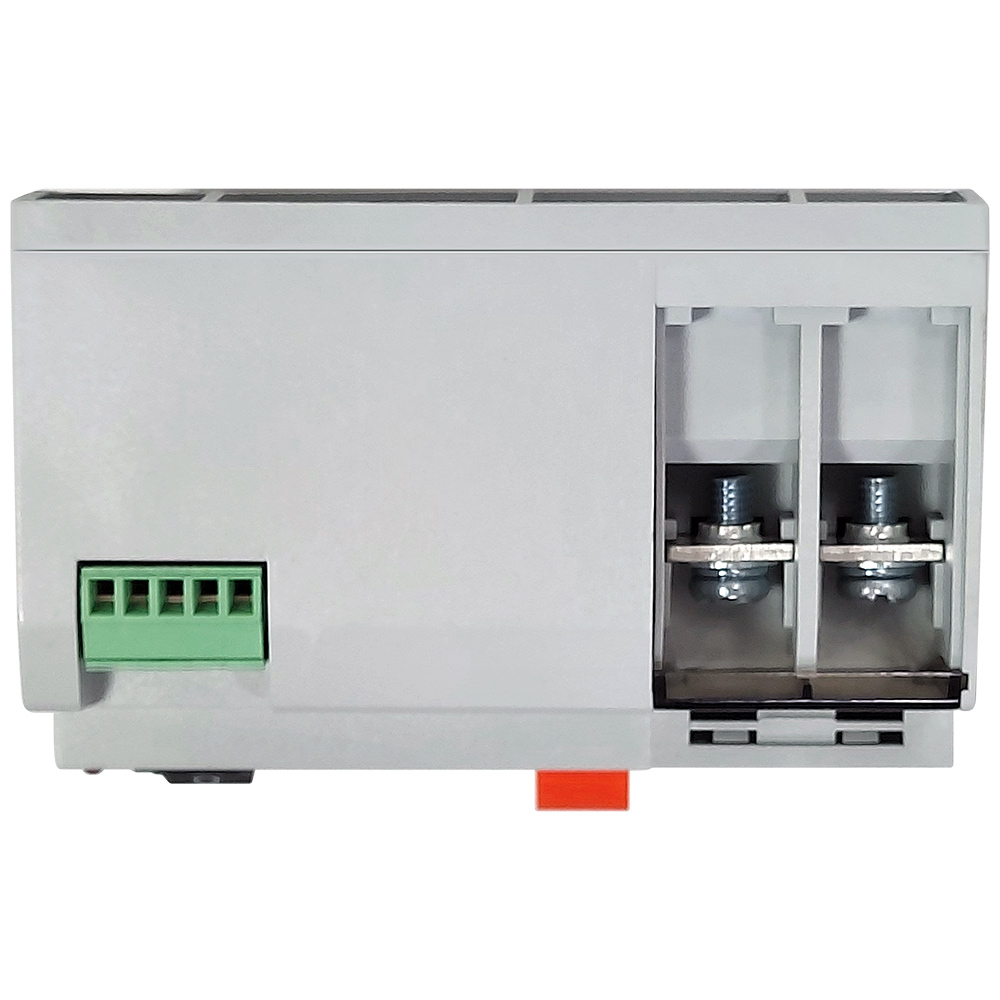
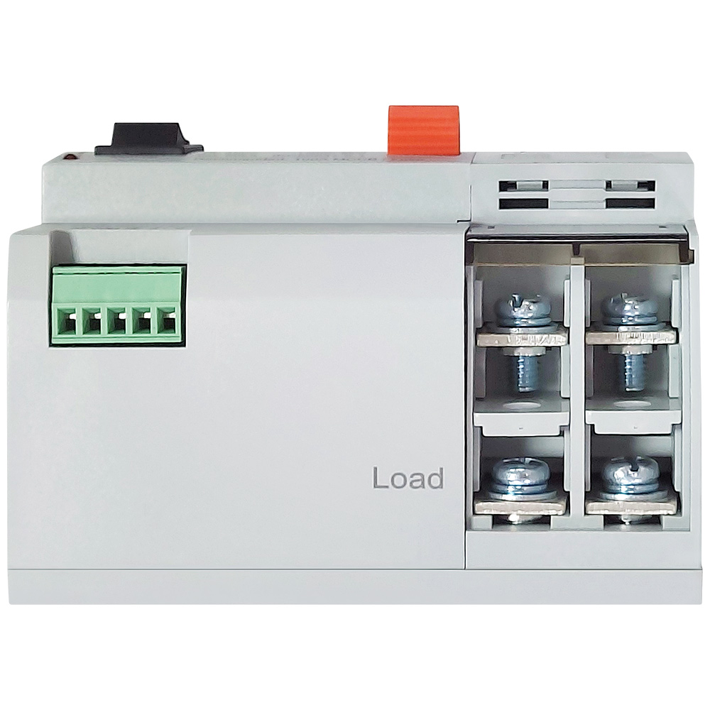
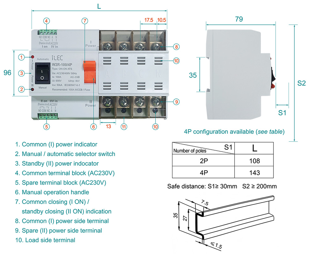
Description and Dimensions
Structural features and functions
The switch has the advantages of small volume, beautiful appearance, reliable conversion, convenient installation and maintenance, and long service life. The switch can realize automatic or manual conversion between common (I) power supply and standby (II) power supply.
Automatic conversion: Automatic charge and non-automatic recovery: When the common (I) power supply power off (or phase failure), the switch will automatically switch to the standby (II) power supply. And when the common (I) power supply back to normal, the switch remains in the standby (II) power supply and does not automatically return to the common (I) power supply. The switch has short switching time (millisecond level) in automatic state, which can realize uninterrupted power supply to power grid.
Manual conversion: When the switch is in the manual state, it can realize the conversion between the manual common power supply and the standby (II) power supply.
Normal working conditions
- The air temperature is from -5°C to 40°C, the average value within 24 hours should not be over 35°C.
- The relative humidity should not exceed 50% at max temperature +40°C, the higher relative humidity is permissible at lower temperature, for instance, 90% at +20°C, but the condensation will be produced due to temperature change, which should be considered.
- The altitude of mounting place should not exceed 2000m. Classification: IV.
- Inclination is not more than ±23°C.
- Pollution grade: 3.
Technical specification
| Model name | W2R-100/2P | |
| Rated current (Ie) | 16A, 20A, 25A, 32A, 40A, 50A, 63A, 80A, 100A | |
| Use category | AC-33B | |
| Rated working voltage (Ue) | AC 400/50Hz | |
| Rated insulation voltage (Ui) | AC 690V/50Hz | |
| Rated imoulse withstand voltage (Uimp) | 8kV | |
| Rated short-circuit limiting current (Iq) | 50kA | |
| Service life (times) |
Mechanical | 5000 |
| Electrical | 2000 | |
| Pole No. | 2P | |
| Classification | PC grade: can be manufactured and withstood without short circuit current | |
| Short circuit protection device (fuse) | RT16-00-100A | |
| Control circuit | Rated control voltage US: AC 230V, 50Hz Normal working conditions: 85%Us - 110%Us |
|
| Auxiliary circuit | Contact capacity of contact converter: AC230V 50Hz Ie=5y | |
| Conversion time of contactor | < 30ms | |
| Operation conversion time | < 30ms | |
| Return conversion time | < 30ms | |
| Power off time | < 30ms | |
| Operating temperature | from -5º to 40ºC | |
| Weigt (kg) | 2P: 0.62kg | |
Matters needing attention
- It is strictly prohibited to manually switch the switch in the automatic state. The switch must be manually operated under the manual state
- It must ensure that the product is not electrified when maintaining or overhauling; After the maintenance or overhaul is completed, the dual power supply controller shall be restored to the automatic state.
- The switch can work reliably at 85%-110% of the rated working voltage. When the voltage is too low, the temperature rise of the coil will increase, which may cause the coil to burn out.
- Please check the integrity of the switch before installation. Check the flexibility of the transmission and detect the load generation and disconnection conditions at each stage of the normal and standby power supplies.
- If the installation cannot be carried out according to the correct steps due to wiring and other reasons, please contact us. The safe distances S1 and S2 should not be lower than the labels in the following figure.
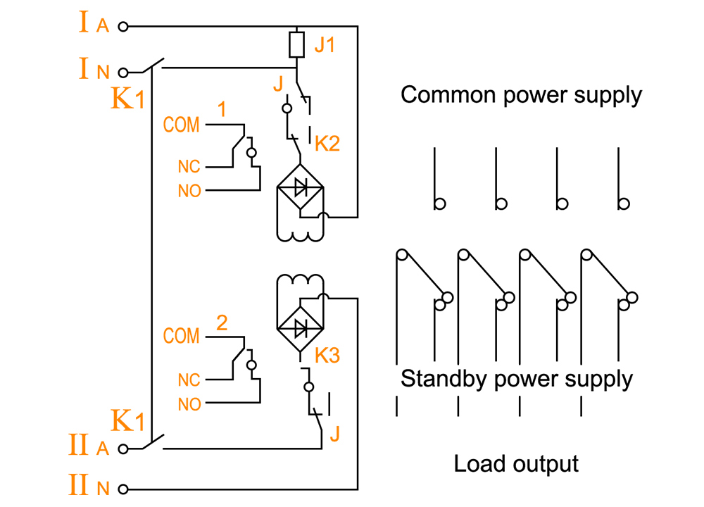
Internal schematic diagram of switch
- K1: manual/Automatic selector switch
- K2 & K3: Internal valve switch
- J1: AC260V relay
- 1: Passive signal output of common power supply
- 2: Passive signal output of standby power supply
Use and maintenance
- Please check the integrity of the switch before installation. Check the flexibility of the transmission and detect the load generation and disconnection conditions at each stage of the normal and standby power supplies.
- If the installation cannot be carried out according to the correct steps due to wiring and other reasons, please contact us. The safe distances S1 and S2 should not be lower than the mark in the above figure.
- Maintenance and inspection shall be operated by professionals and all power supplies shall be cut off in advance.
- Check whether the contact part of each electrical appliance is reliable and compact before, and whether the fuse is in good condition.
- Detection control voltage: 50Hz AC230V, and the conductor in the control circuit cannot be too long. The cross-sectional area of copper wire should not be greater than 2.0mm².
- According to the installation requirements of power distribution system, please provide appropriate circuit breakers to ensure the safety of staff and equipment.
- The switch shall be stored in an environment equivalent to its normal operating conditions, with dust-proofing, moisture-proofing, and impact-protection measures.
- During operation, routine inspections shall be carried out regularly (e.g., every three months of operation). Proper functionality must be verified by testing power supply switching.
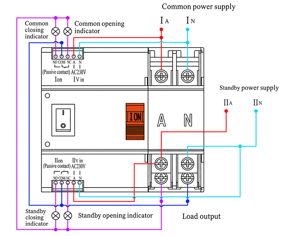
Connection diagram
■ ATS iLEC W2R-100/2P
Installation and Disassembly
- Installation and disassembly method: This switch is installed with 35mm standard guide rail, and the thickness of guide rail sheet metal is less than 1.5mm
- Buckle the lower end of the guide rail groove at the rear of the product into the guide rail first, then push the product upward and press it inward, and install it in place.
- Disassembly method: Push the product up and then pull it out to complete disassembly.
Resources & Support
- Technical documents: [English] [Vietnamese]
-
Pricing & Ordering: View Details
[W2R-100/2P]
